4.5.3 DDR I/O Voltage Selection
There is a DIP switch provided on the J721E SoM to select the SoC’s DDR and LPDDR4 memory I/O supply for
the LPDDR4/LPDDR4x.
Currently, the J721E device does not support LPDDR4x. This support may be added at a later date. The EVM
does support this feature if/when support is added to the silicon.
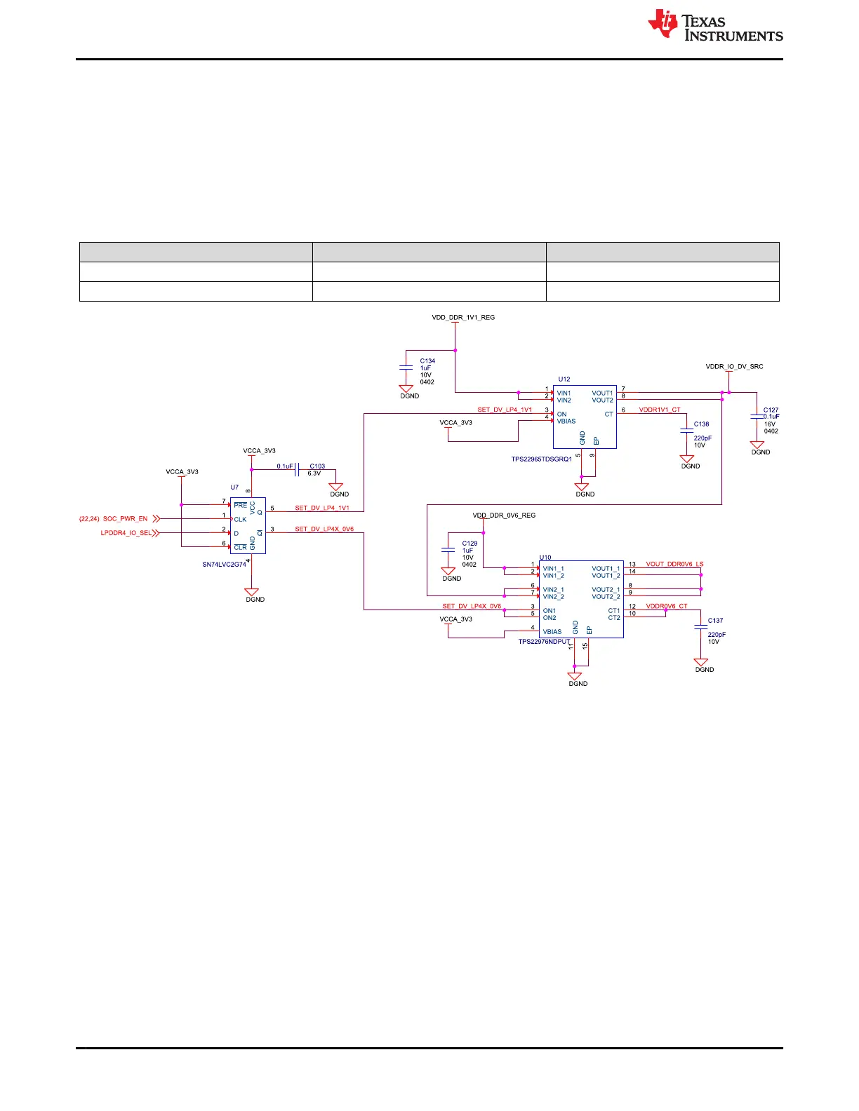
The DIP switch SW1 Bit 1 provides an option to change the logic of D Flip-Flop (U7) that controls the Load
Switches TPS22965TDSGRQ1 and TPS22976NDPUT to decide the I/O supply voltages.
Table 4-4. DDR I/O Voltage Selection
SW1 Bit 1 SDRAM_TYPE Selected DDR I/O Voltage
LOW LPDDR4X 0.6V
HIGH LPDDR4 1.1V
Figure 4-6. LPDDR4 IO Voltage Selection Circuit
J721E EVM Hardware Architecture www.ti.com
34 Jacinto7 J721E/DRA829/TDA4VM Evaluation Module (EVM) SPRUIS4D – MAY 2020 – REVISED MARCH 2022
Submit Document Feedback
Copyright © 2022 Texas Instruments Incorporated