CDCI6214
CLK GEN
CP Board
CDCI6214
CLK GEN
Quad Port
ENET Exp
U4
U17
SOC_I2C0_SCL/SDA
CDCI2_RSTz
10k
3.3 V
CPB:I2C0:U31-P17
SoM
Analog
Switch
SN74LVC2G66
U5
CDCI_I2C0
CDCI_I2C_SEL
10k
Low: Disconnect
High: Connect
CPB:I2C0:U31-P22 (ENET_2CMUX_SELL)
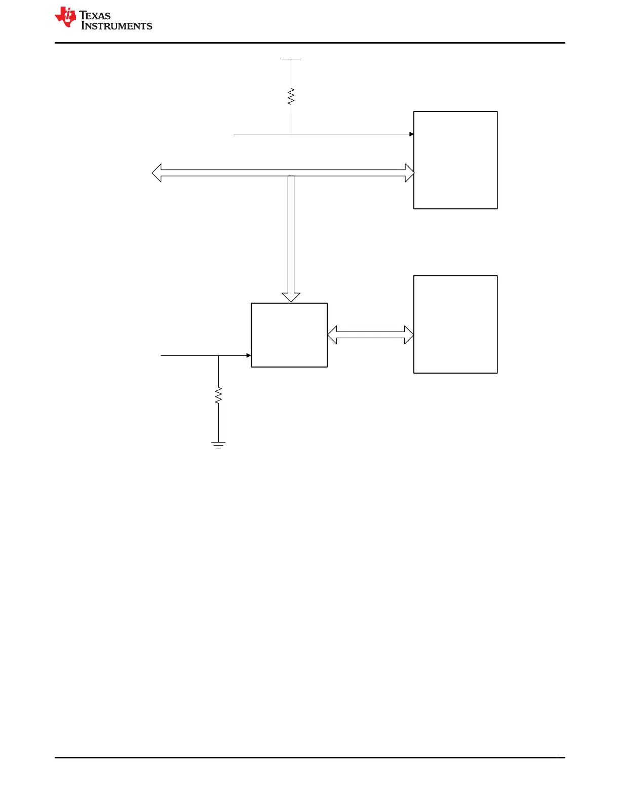
Figure 4-17. Quad-SGMII Board I2C
Coupling capacitors (0.1 µF) added in series at the respective driver ends on the QSGMII data signals.
The address and clock configurations are shown below:
• PHY0: 10000 0X10
• PHY1: 10001 0X11
• PHY2: 10010 0X12
• PHY3: 10011 0X13
www.ti.com J721E EVM Hardware Architecture
SPRUIS4D – MAY 2020 – REVISED MARCH 2022
Submit Document Feedback
Jacinto7 J721E/DRA829/TDA4VM Evaluation Module (EVM) 51
Copyright © 2022 Texas Instruments Incorporated