7.3 Recommended Operating Conditions (continued)
over operating free-air temperature range (unless otherwise noted)
MIN NOM MAX UNIT
f
ULPCLK (PD0 bus clock)
ULPCLK frequency 40 MHz
(1) Connect C
VDD
and C
VCORE
between VDD/VSS and VCORE/VSS, respectively, as close to the device pins as possible. A low-ESR
capacitor with at least the specified value and tolerance of ±20% or better is required for C
VDD
and C
VCORE
.
(2) The VCORE pin must only be connected to C
VCORE
. Do not supply any voltage or apply any external load to the VCORE pin.
(3) Wait states are managed automatically by the system controller (SYSCTL) and do not need to be configured by application software
unless MCLK is sourced from a high speed clock source (HSCLK sourced from HFCLK or SYSPLL).
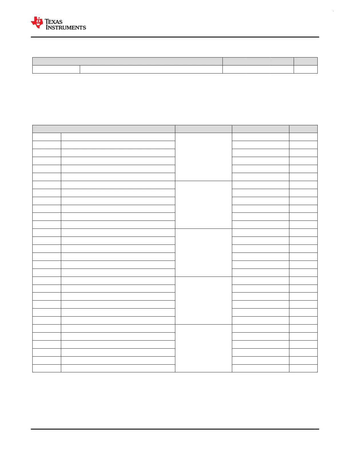
7.4 Thermal Information
THERMAL METRIC
(1)
PACKAGE VALUE UNIT
R
θJA
Junction-to-ambient thermal resistance
LQFP-64 (PM)
61.8 °C/W
R
θJC(top)
Junction-to-case (top) thermal resistance 22.0 °C/W
R
θJB
Junction-to-board thermal resistance 33.0 °C/W
Ψ
JT
Junction-to-top characterization parameter 1.7 °C/W
Ψ
JB
Junction-to-board characterization parameter 32.7 °C/W
R
θJC(bot)
Junction-to-case (bottom) thermal resistance N/A °C/W
R
θJA
Junction-to-ambient thermal resistance
VQFN-48 (RGZ)
30.1 °C/W
R
θJC(top)
Junction-to-case (top) thermal resistance 20.7 °C/W
R
θJB
Junction-to-board thermal resistance 12.5 °C/W
Ψ
JT
Junction-to-top characterization parameter 0.3 °C/W
Ψ
JB
Junction-to-board characterization parameter 12.4 °C/W
R
θJC(bot)
Junction-to-case (bottom) thermal resistance 4.2 °C/W
R
θJA
Junction-to-ambient thermal resistance
LQFP-48 (PT)
69.7 °C/W
R
θJC(top)
Junction-to-case (top) thermal resistance 28.0 °C/W
R
θJB
Junction-to-board thermal resistance 33.4 °C/W
Ψ
JT
Junction-to-top characterization parameter 2.7 °C/W
Ψ
JB
Junction-to-board characterization parameter 33.2 °C/W
R
θJC(bot)
Junction-to-case (bottom) thermal resistance N/A °C/W
R
θJA
Junction-to-ambient thermal resistance
VQFN-32 (RHB)
32.1 °C/W
R
θJC(top)
Junction-to-case (top) thermal resistance 23.6 °C/W
R
θJB
Junction-to-board thermal resistance 13.0 °C/W
Ψ
JT
Junction-to-top characterization parameter 0.3 °C/W
Ψ
JB
Junction-to-board characterization parameter 13.0 °C/W
R
θJC(bot)
Junction-to-case (bottom) thermal resistance 3.3 °C/W
R
θJA
Junction-to-ambient thermal resistance
VSSOP-28 (DGS28)
78.9 °C/W
R
θJC(top)
Junction-to-case (top) thermal resistance 38.6 °C/W
R
θJB
Junction-to-board thermal resistance 41.3 °C/W
Ψ
JT
Junction-to-top characterization parameter 3.4 °C/W
Ψ
JB
Junction-to-board characterization parameter 41.0 °C/W
R
θJC(bot)
Junction-to-case (bottom) thermal resistance N/A °C/W
(1) For more information about traditional and new thermal metrics, see the Semiconductor and IC Package Thermal Metrics application
report.
www.ti.com
MSPM0G3507, MSPM0G3506, MSPM0G3505
SLASEX6A – FEBRUARY 2023 – REVISED JUNE 2023
Copyright © 2023 Texas Instruments Incorporated
Submit Document Feedback
29
Product Folder Links: MSPM0G3507 MSPM0G3506 MSPM0G3505
 Loading...


