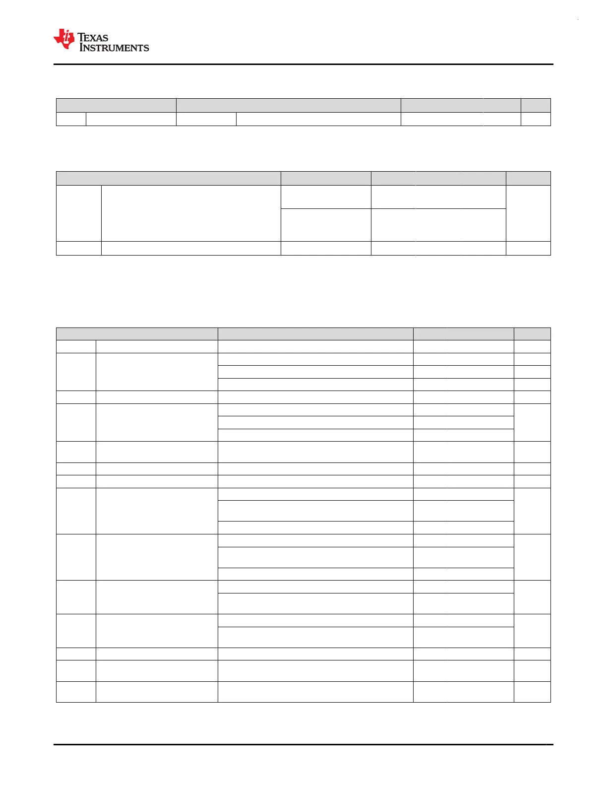
7.10.2 Switching Characteristics (continued)
over recommended ranges of supply voltage and operating free-air temperature (unless otherwise noted)
PARAMETER TEST CONDITIONS MIN TYP MAX UNIT
t
f
Output fall time ODIO VDD ≥ 1.71V, FM
+
, CL= 20pF-100pF 20*VDD/5.5 120 ns
7.11 Analog Mux VBOOST
over operating free-air temperature range (unless otherwise noted)
PARAMETER TEST CONDITIONS MIN TYP MAX UNIT
I
VBST
VBOOST current adder
MCLK/ULPCLK is
LFCLK
0.8
uA
MCLK/ULPCLK is
not LFCLK, SYSOSC
frequency is 4MHz
8.5
t
START,VBST
VBOOST startup time 12 us
7.12 ADC
7.12.1 Electrical Characteristics
over recommended ranges of supply voltage and operating free-air temperature (unless otherwise noted), all TYP values are
measured at 25℃ and all accuracy parameters are measured using 12-bit resolution mode (unless otherwise noted)
PARAMETER TEST CONDITIONS MIN TYP MAX UNIT
Vin
(ADC)
Analog input voltage range
(1)
Applies to all ADC analog input pins 0 VDD V
V
R+
Positive ADC reference voltage
V
R+
sourced from VDD VDD V
V
R+
sourced from external reference pin (VREF+) 1.4 VDD V
V
R+
sourced from internal reference (VREF) VREF V
V
R-
Negative ADC reference voltage 0 V
F
S
ADC sampling frequency
RES = 0x0 (12-bit mode) 4.0
MspsRES = 0x1 (10-bit mode) 4.36
RES = 0x2 (8-bit mode) 5.33
I
(ADC)
Operating supply current
into VDD terminal
F
S
= 4MSPS, V
R+
= VDD 1456 μA
C
S/H
ADC sample-and-hold capacitance 3.3 pF
Rin ADC input resistance 0.5 kΩ
ENOB Effective number of bits
External reference
(2)
11.1
bit
External reference
(4)
, HW Averaging Enabled, 16 Samples
and 2bit shift
12.4
Internal reference, V
R+
= VREF = 2.5V 10.16
SNR Signal-to-noise ratio
External reference
(2)
69
dB
External reference
(4)
, HW Averaging Enabled, 16 Samples
and 2bit shift
79
Internal reference, V
R+
= VREF = 2.5V 63.1
PSRR
DC
Power supply rejection ratio, DC
External reference
(2)
, VDD = VDD
(min)
to VDD
(max)
62
dB
VDD = VDD
(min)
to VDD
(max)
Internal reference, V
R+
= VREF = 2.5V
64.2
PSRR
AC
Power supply rejection ratio, AC
External reference
(2)
, ΔVDD = 0.1 V at 1 kHz 60
dB
ΔVDD = 0.1 V at 1 kHz
Internal reference, V
R+
= VREF = 2.5V
55.5
T
wakeup
ADC Wakeup Time Assumes internal reference is active 1.22 us
V
SupplyMon
Supply Monitor voltage divider
(VDD/3) accuracy
ADC input channel: Supply Monitor
(3)
-1.5 1.5 %
I
SupplyMon
Supply Monitor voltage divider current
consumption
ADC input channel: Supply Monitor 9.7 uA
(1) The analog input voltage range must be within the selected ADC reference voltage range V
R+
to V
R–
for valid conversion results.
(2) All external reference specifications are measured with V
R+
= VREF+ = VDD = 3.3V and V
R-
= VREF- = VSS = 0V
www.ti.com
MSPM0G3507, MSPM0G3506, MSPM0G3505
SLASEX6A – FEBRUARY 2023 – REVISED JUNE 2023
Copyright © 2023 Texas Instruments Incorporated
Submit Document Feedback
39
Product Folder Links: MSPM0G3507 MSPM0G3506 MSPM0G3505
 Loading...


