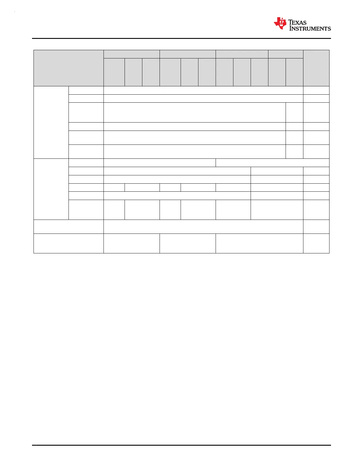
Table 8-1. Supported Functionality by Operating Mode (continued)
OPERATING MODE
RUN SLEEP STOP STANDBY
SHUTDOWN
RUN0
RUN1
RUN2
SLEEP0
SLEEP1
SLEEP2
STOP0
STOP1
STOP2
STANDBY0
STANDBY1
PD0
Peripherals
TIMG0, TIMG8 OPT OFF
RTC OPT OFF
UART0,
UART1,
UART2
OPT OPT
(2)
OFF
I2C0, I2C1 OPT OPT
(2)
OFF
GPIOA,
GPIOB
(3)
OPT OPT
(2)
OFF
WWDT0,
WWDT1
OPT DIS OFF
Analog
TRNG OPT OFF
ADC0, ADC1
(3)
OPT NS (triggers supported) OFF
DAC0 OPT NS OFF
OPA0, OPA1 OPT NS OPT NS OPT NS OFF
GPAMP OPT NS OFF
COMP0,
COMP1,
COMP2
OPT OPT
(ULP)
OPT OPT
(ULP)
OPT OPT
(ULP)
OFF
IOMUX and IO Wakeup EN
DIS w/
WAKE
Wake Sources N/A ANY IRQ PD0 IRQ
IOMUX,
NRST,
SWD
(1) If STOP0 is entered from RUN1 (SYSOSC enabled but MCLK sourced from LFCLK), SYSOSC remains enabled as it was in RUN1,
and ULPCLK remains at 32 kHz as it was in RUN1. If STOP0 is entered from RUN2 (SYSOSC was disabled and MCLK was sourced
from LFCLK), SYSOSC remains disabled as it was in RUN2, and ULPCLK remains at 32 kHz as it was in RUN2.
(2) When using the STANDBY1 policy for STANDBY, only TIMG0, TIMG8, and the RTC are clocked. Other PD0 peripherals can generate
an asynchronous fast clock request upon external activity but are not actively clocked.
(3) For ADCx and GPIO Ports A and B, the digital logic is in PD0 and the register interface is in PD1. These peripherals support fast
single-cycle register access when PD1 is active and also support basic operation down to STANDBY mode where PD0 is still active.
8.3 Power Management Unit (PMU)
The power management unit (PMU) generates the internally regulated core supplies for the device and provides
supervision of the external supply (VDD). The PMU also contains the bandgap voltage reference used by the
PMU itself as well as analog peripherals. Key features of the PMU include:
• Power-on reset (POR) supply monitor
• Brown-out reset (BOR) supply monitor with early warning capability using three programmable thresholds
• Core regulator with support for RUN, SLEEP, STOP, and STANDBY operating modes to dynamically balance
performance with power consumption
• Parity-protected trim to immediately generate a power-on reset (POR) in the event that a power management
trim is corrupted
For more details, see the PMU chapter of the MSPM0 G-Series 80-MHz Microcontrollers Technical Reference
Manual.
8.4 Clock Module (CKM)
The clock module provides the following oscillators:
• LFOSC: Internal low-frequency oscillator (32KHz)
MSPM0G3507, MSPM0G3506, MSPM0G3505
SLASEX6A – FEBRUARY 2023 – REVISED JUNE 2023
www.ti.com
54 Submit Document Feedback
Copyright © 2023 Texas Instruments Incorporated
Product Folder Links: MSPM0G3507 MSPM0G3506 MSPM0G3505
 Loading...


