(5) Sector program time is defined as the time from when the first word program command is triggered until the final word program
command completes and the interrupt flag is set in the flash controller. This time includes the time needed for software to load each
flash word (after the first flash word) into the flash controller during programming of the sector.
(6) Flash word size is 64 data bits (8 bytes). On devices with ECC, the total flash word size is 72 bits (64 data bits plus 8 ECC bits).
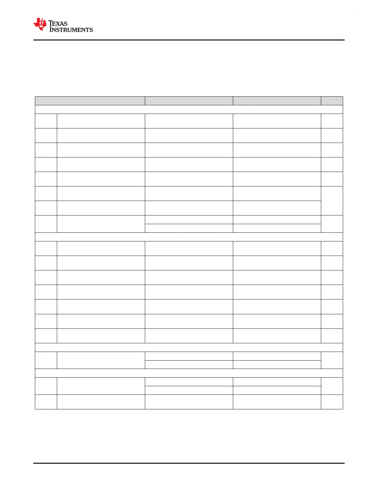
7.8 Timing Characteristics
VDD=3.3V, T
a
=25℃ (unless otherwise noted)
PARAMETER TEST CONDITIONS MIN TYP MAX UNIT
Wakeup Timing
t
WAKE,
SLEEP1
Wakeup time from SLEEP1 to RUN
(1)
1.6 us
t
WAKE,
SLEEP2
Wakeup time from SLEEP2 to RUN
(1)
2.2 us
t
WAKE,
STANDBY0
Wakeup time from STANDBY0 to RUN
(1)
22.7 us
t
WAKE,
STANDBY1
Wakeup time from STANDBY1 to RUN
(1)
22.7 us
t
WAKE,
STOP0
Wakeup time from STOP0 to RUN
(SYSOSC enabled)
(1)
19.7 us
t
WAKE,
STOP1
Wakeup time from STOP1 to RUN
(SYSOSC enabled)
(1)
21.2
us
t
WAKE,
STOP2
Wakeup time from STOP2 to RUN
(SYSOSC disabled)
(1)
20.5
t
WAKEUP,
SHDN
Wakeup time from SHUTDOWN to
RUN
(2)
Fast boot enabled 250
us
Fast boot disabled 270
Asynchronous Fast Clock Request Timing
t
DELAY,
SLEEP1
Delay time from edge of asynchronous
request to first 32MHz MCLK edge
Mode is SLEEP1 0.34 us
t
DELAY,
SLEEP2
Delay time from edge of asynchronous
request to first 32MHz MCLK edge
Mode is SLEEP2 0.95 us
t
DELAY,
STANDBY0
Delay time from edge of asynchronous
request to first 32MHz MCLK edge
Mode is STANDBY0 3.1 us
t
DELAY,
STANDBY1
Delay time from edge of asynchronous
request to first 32MHz MCLK edge
Mode is STANDBY1 3.2 us
t
DELAY,
STOP0
Delay time from edge of asynchronous
request to first 32MHz MCLK edge
Mode is STOP0 1.0 us
t
DELAY,
STOP1
Delay time from edge of asynchronous
request to first 32MHz MCLK edge
Mode is STOP1 2.4 us
t
DELAY,
STOP2
Delay time from edge of asynchronous
request to first 32MHz MCLK edge
Mode is STOP2 1.0 us
Startup Timing
t
START,
RESET
Device cold startup time from reset/
power-up
(3)
Fast boot enabled 271
us
Fast boot disabled 318
NRST Timing
t
RST,
BOOTRST
Pulse length on NRST pin to generate
BOOTRST
ULPCLK≥4MHz 1.5
us
ULPCLK=32kHz 100
t
RST, POR
Pulse length on NRST pin to generate
POR
1 s
(1) The wake-up time is measured from the edge of an external wake-up signal (GPIO wake-up event) to the time that the first instruction
of the user program is executed, with glitch filter disabled (FILTEREN=0x0) and fast wake enabled (FASTWAKEONLY=1) .
(2) The wake-up time is measured from the edge of an external wake-up signal (IOMUX wake-up event) to the time that first instruction of
the user program is executed.
www.ti.com
MSPM0G3507, MSPM0G3506, MSPM0G3505
SLASEX6A – FEBRUARY 2023 – REVISED JUNE 2023
Copyright © 2023 Texas Instruments Incorporated
Submit Document Feedback
33
Product Folder Links: MSPM0G3507 MSPM0G3506 MSPM0G3505
 Loading...


