(3) The start-up time is measured from the time that VDD crosses VBOR0- (cold start-up) to the time that the first instruction of the user
program is executed.
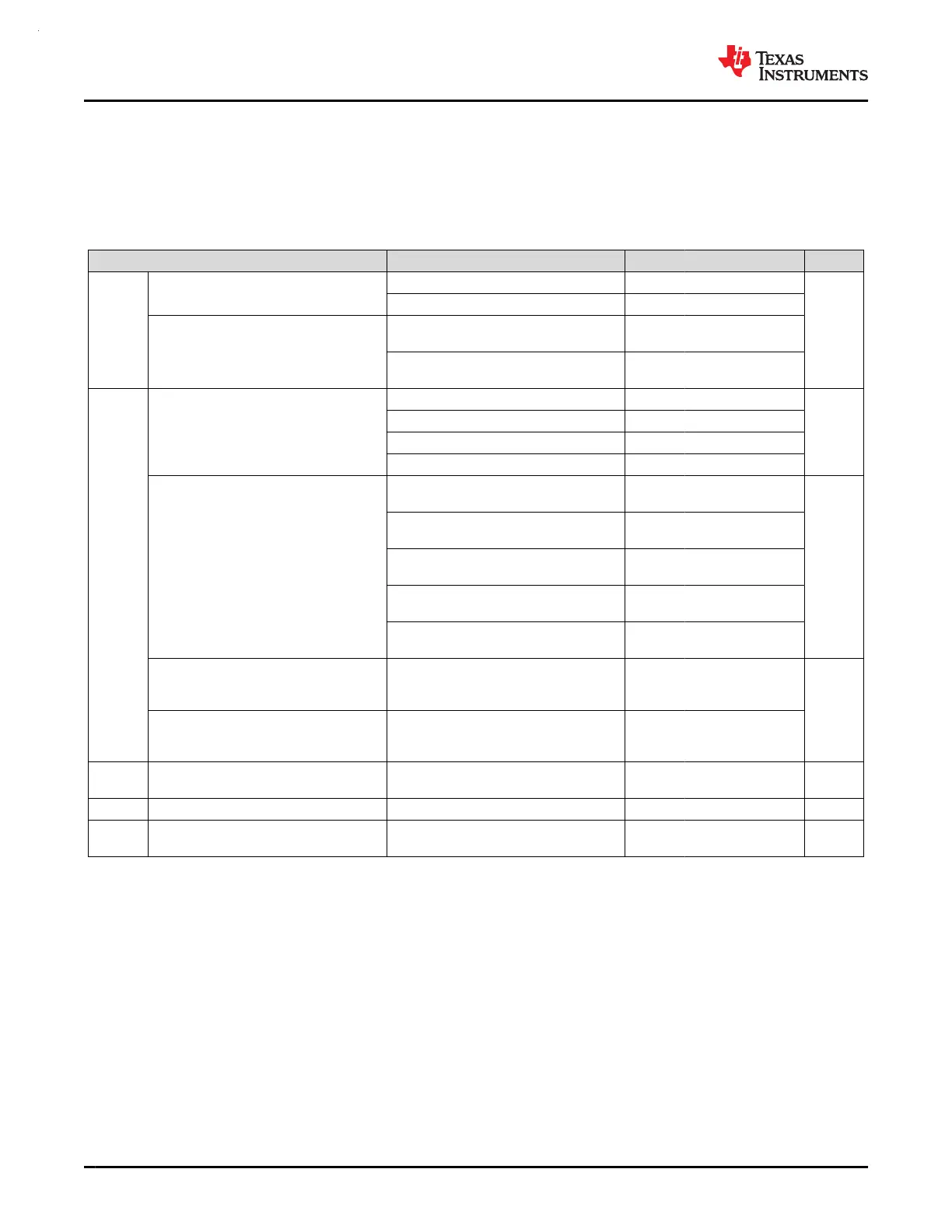
7.9 Clock Specifications
7.9.1 System Oscillator (SYSOSC)
over operating free-air temperature range (unless otherwise noted)
PARAMETER TEST CONDITIONS MIN TYP MAX UNIT
f
SYSOSC
Factory trimmed SYSOSC frequency
SYSOSCCFG.FREQ=00 (BASE) 32
MHz
SYSOSCCFG.FREQ=01 4
User trimmed SYSOSC frequency
SYSOSCCFG.FREQ=10,
SYSOSCTRIMUSER.FREQ=10
24
SYSOSCCFG.FREQ=10,
SYSOSCTRIMUSER.FREQ=01
16
f
SYSOSC
SYSOSC frequency accuracy when
frequency correction loop (FCL) is
enabled and an ideal ROSC resistor is
assumed
(1)
(2)
SETUSEFCL=1, T
a
= 25 ℃ -0.41 0.58
%
SETUSEFCL=1, -40 ℃ ≤ T
a
≤ 85 ℃ -0.80 0.93
SETUSEFCL=1, -40 ℃ ≤ T
a
≤ 105 ℃ -0.80 1.09
SETUSEFCL=1, -40 ℃ ≤ T
a
≤ 125 ℃ -0.80 1.30
SYSOSC accuracy when frequency
correction loop (FCL) is enabled with
R
OSC
resistor put at R
OSC
pin, for factory
trimmed frequencies
(1)
SETUSEFCL=1, T
a
= 25 ℃, ±0.1%
±25ppm R
OSC
–0.5 0.7
%
SETUSEFCL=1, -40 ℃ ≤ T
a
≤ 85
℃, ±0.1% ±25ppm R
OSC
-1.1 1.2
SETUSEFCL=1, -40 ℃ ≤ T
a
≤ 85
℃, ±0.1% ±25ppm R
OSC
–1.1 1.2
SETUSEFCL=1, -40 ℃ ≤ T
a
≤ 105
℃, ±0.1% ±25ppm R
OSC
–1.1 1.4
SETUSEFCL=1, -40 ℃ ≤ T
a
≤ 125 ℃,
±0.1% ±25ppm R
OSC
–1.1 1.7
SYSOSC accuracy when frequency
correction loop (FCL) is disabled, 32MHz
SETUSEFCL=0,
SYSOSCCFG.FREQ=00, -40 ℃ ≤ T
a
≤
125 ℃
–2.6 1.8
%
SYSOSC accuracy when frequency
correction loop (FCL) is disabled, for
factory trimmed frequencies, 4MHz
SETUSEFCL=0,
SYSOSCCFG.FREQ=01, -40 ℃ ≤ T
a
≤
125 ℃
–2.7 2.3
f
SYSOSC
External resistor put between ROSC pin
and VSS
(1)
SETUSEFCL=1 100 kΩ
f
SYSOSC
Settling time to target accuracy
(3)
SETUSEFCL=1, ±0.1% 25ppm R
OSC
(1)
30 us
f
SYSOSC
f
SYSOSC
additional undershoot accuracy
during t
settle
(3)
SETUSEFCL=1, ±0.1% 25ppm R
OSC
(1)
-11 %
(1) The SYSOSC frequency correction loop (FCL) enables high SYSOSC accuracy via an external reference resistor (R
OSC
) which must
be connected between the device ROSC pin and VSS when using the FCL. Accuracies are shown for a ±0.1% ±25ppm R
OSC
; relaxed
tolerance resistors may also be used (with reduced SYSOSC accuracy). See the SYSOSC section of the technical reference manual
for details on computing SYSOSC accuracy for various R
OSC
accuracies. R
OSC
does not need to be populated if the FCL is not
enabled.
(2) Represents the device accuracy only. The tolerance and temperature drift of the ROSC resistor used must be combined with this spec
to determine final accuracy. Performance for a ±0.1% ±25ppm R
OSC
is given as a reference point.
(3) When SYSOSC is waking up (for example, when exiting a low power mode) and FCL is enabled, the SYSOSC will initially undershoot
the target frequency f
SYSOSC
by an additional error of up to f
settle,SYSOSC
for the time t
settle,SYSOSC
, after which the target accuracy is
achieved.
MSPM0G3507, MSPM0G3506, MSPM0G3505
SLASEX6A – FEBRUARY 2023 – REVISED JUNE 2023
www.ti.com
34 Submit Document Feedback
Copyright © 2023 Texas Instruments Incorporated
Product Folder Links: MSPM0G3507 MSPM0G3506 MSPM0G3505
 Loading...


