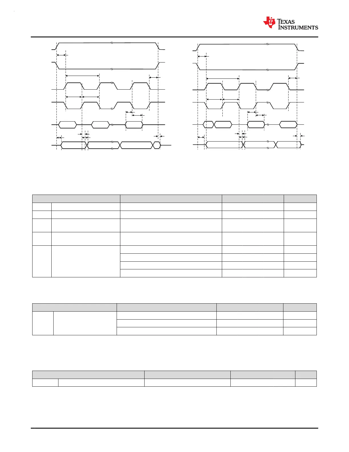
CS
(inverted)
CS
t
CS, LEAD
t
CS, ACC
t
CS, LAG
t
CS, DIS
t
SU,PI
t
HD,PI
t
VALID,PO
t
HD,PO
SCLK
(SPO = 0)
PICO
SCLK
(SPO = 1)
POCI
1 / f
SPI
t
SCLK_H/L
t
SCLK_H/L
Peripheral Mode, SPH = 0
CS
(inverted)
CS
t
CS, LEAD
t
CS, ACC
t
CS, LAG
t
CS, DIS
t
SU,PI
t
HD,PI
t
VALID,PO
t
HD,PO
SCLK
(SPO = 0)
PICO
SCLK
(SPO = 1)
POCI
1 / f
SPI
t
SCLK_H/L
t
SCLK_H/L
Peripheral Mode, SPH = 1
Figure 7-7. SPI timing diagram - Peripheral Mode
7.21 UART
over operating free-air temperature range (unless otherwise noted)
PARAMETERS TEST CONDITIONS MIN TYP MAX UNIT
f
UART
UART input clock frequency UART in Power Domain1 80 MHz
f
UART
UART input clock frequency UART in Power Domain0 40 MHz
f
BITCLK
BITCLK clock frequency(equals
baud rate in MBaud)
UART in Power Domain1 10 MHz
f
BITCLK
BITCLK clock frequency(equals
baud rate in MBaud)
UART in Power Domain0 5 MHz
t
SP
Pulse duration of spikes
suppressed by input filter
AGFSELx = 0 6 ns
AGFSELx = 1 14 35 ns
AGFSELx = 2 22 60 ns
AGFSELx = 3 35 90 ns
7.22 TIMx
over operating free-air temperature range (unless otherwise noted)
PARAMETERS TEST CONDITIONS MIN TYP MAX UNIT
t
res
Timer resolution time
TIMx in Power Domain 1, f
TIMxCLK
= 80MHz 12.5 ns
TIMx in Power Domain 0, f
TIMxCLK
= 40MHz 25 ns
1 t
TIMxCLK
7.23 TRNG
7.23.1 TRNG Electrical Characteristics
over operating free-air temperature range (unless otherwise noted)
PARAMETER TEST CONDITIONS MIN TYP MAX UNIT
TRNG
IACT
TRNG active current TRNG clock = 20MHz 75 µA
MSPM0G3507, MSPM0G3506, MSPM0G3505
SLASEX6A – FEBRUARY 2023 – REVISED JUNE 2023
www.ti.com
50 Submit Document Feedback
Copyright © 2023 Texas Instruments Incorporated
Product Folder Links: MSPM0G3507 MSPM0G3506 MSPM0G3505
 Loading...


