14: Local Zone Expander
The Premier 8XE Local Zone Expander can be plugged on to the
main PCB. The local expander provides an additional 8
programmable zones (see page 14).
15: Speech Module
A four channel Speech Module can be plugged on to the main PCB
(SK1). This connector is only fitted on the Premier 816Plus and
Premier 832 control panels.
16: Box Tamper Switch
Box tamper protection for the main control panel.
17: Power Light
On steady when either AC or standby battery is present. Flashes
when the on-board communicator is dialling or sending data.
18: Electronic Fuses
The PCB is protected using electronic PTC fuses:
F1 (2.5 Amp) Battery fuse
F2 (900mA) Auxiliary 12V power fuse
F3 (900mA) Siren/Bell output fuse
F4 (900mA) Network fuse
To reset a fuse, remove all load from the protected circuit, wait 10
seconds, then reconnect.
19: Telephone Line Connections
Telephone line connections (see page 19).
20: RJ11 Telephone Line Connector
An RJ11 connector is provided so that the panel can be connected
to the telephone line via a standard RJ11 patch lead.
21: Engineers Keypad Connection
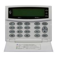
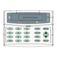
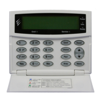
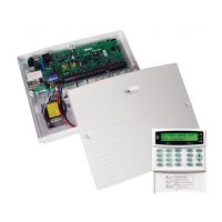
An engineer’s keypad (Premier LCD keypad and interface lead) can
be temporarily plugged onto this connector to allow system
programming and testing.
22: Network Data Indicator LEDs
The red transmit (Tx) LED indicates that data is flowing out of the
control panel and normally flashes very quickly. The green receive
(Rx) LED indicates that data is flowing into the control panel. The
green LED flashes faster as more devices are connected to the data
network.
23: Electronic Fuse Fault Indicator LEDs
Electronic fuses F2-F4 have red indicator LEDs, which light up when
the relevant fuse is open circuit (fault).
24: Battery Kick Start Pins
The control panel has a deep discharge protection circuit that
prevents the standby battery from being fully discharged. When
powering up the control panel without AC Mains (battery only), the
centre and either outer pins must be shorted together in order to
bring the battery into circuit.
25: Battery Charge Current Selector
When using a 7Ah standby battery the charge current selector
should be set to 300mA. If a 17Ah battery is connected (metal
cabinet only) the selector should be set to the 750mA position.
Power Supply Ratings
All Models (Large & Small Polymer)
Current
 Loading...

