CONTENTS
USING THE PRODUCT SAFETY ............................................................................................................... Ⅰ-Ⅲ
1. PDS-A SERIES ________________________________________________________ 1
1-1. About This Manual .......................................................................................................................... 1
1-2. Outline of Product ............................................................................................................................ 1
1-3. Features........................................................................................................................................... 1
1-3-1. PDS-A Power Supply Unit ........................................................................................................ 1
1-3-2. IF-71RS (option) ....................................................................................................................... 2
1-3-3. IF-70GU (option) ....................................................................................................................... 2
1-3-4. IF-71LU (option) ....................................................................................................................... 2
1-3-5. Cable for master-slave operation (option) ................................................................................ 2
1-3-6. Handle (option) ......................................................................................................................... 2
2. PRIOR TO USE _______________________________________________________ 3
2-1. Accessories ..................................................................................................................................... 3
2-2. Connecting the power cable ............................................................................................................ 4
2-3. Connecting to the output terminals ................................................................................................. 4
2-3-1. Attaching the output grounding cable ....................................................................................... 4
2-3-2. Connecting the voltage remote sensing cables ....................................................................... 5
2-3-3. Attaching the rear output terminal cover .................................................................................. 5
2-4. Caution on Connecting to a Capacitive Load .................................................................................. 5
2-5. Connecting the protective grounding terminal on the bottom face ................................................. 6
2-6. Caution on mounting the unit in a rack ........................................................................................... 6
2-7. Connecting the Power Cable to the Primary Power ....................................................................... 6
2-8. Installation Environments ................................................................................................................ 7
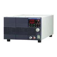
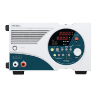
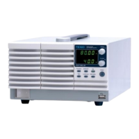
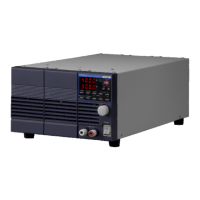
3. PANELS _____________________________________________________________ 8
3-1. Front Panel ...................................................................................................................................... 8
3-2. Operation Panel............................................................................................................................... 9
3-3. Rear Panel ..................................................................................................................................... 12
4. GENERAL INSTRUCTIONS_____________________________________________ 15
4-1. Connecting loads ........................................................................................................................... 15
4-2. Alarm .............................................................................................................................................. 16
5. FUNCTIONS AND OPERATION PROCEDURES ____________________________ 17
5-1. Operation modes ........................................................................................................................... 17
5-2. Turning On Power.......................................................................................................................... 17
5-2-1. Display when power is turned on ........................................................................................... 17
5-2-2. Performing a unit scan while using a parallel connection ...................................................... 17
5-2-3. Recalling Settings When Turning on Power, and Saving the Setting Data ........................... 18
5-3. Basic Operation ............................................................................................................................. 19
5-3-1. Voltage setting procedure ....................................................................................................... 19
5-3-2. Current setting procedure ....................................................................................................... 19
5-3-3. Fine adjustment of voltage/current ......................................................................................... 19
5-4. Output Functions ........................................................................................................................... 20
5-5. Memory Function ........................................................................................................................... 20
5-5-1. Storing and recalling preset voltage/current data ....................................................................... 20
5-6. Switching the display in the Voltage/Current Indicator Display. ......................................................... 21
5-6-1. Switching between the set voltage/current display and output voltage/current display......... 21