9-2-4. Adjusting the set current
Modify the internally set voltage to adjust the set current specified by externally set voltage.
A
V
W
W
CC:R
CV: G
OUTPUT
V(W) A(W)
MENU PROTECT CHECK
ESC/ KEY LOCK ENTER/MEM 1 2 3
DIGIT
PRESET/ SEQUENCE
* LOCK/ RMT STEP STOP PAUSE START
1
2
PDS-A series
A
V
W
W
CC:R
CV:G
OUTPUT
V(W) A(W)
MENU PROTECT CHECK
ESC/ KEY LOCK ENTER/MEM 1 2 3
DIGIT
PRESET/ SEQUENCE
* LOCK/ RMT STEP STOP PAUSE START
3
4
5 6
PDS-A series
A
V
W
W
CC:R
CV:G
OUTPUT
V(W) A(W)
MENU PROTECT CHECK
ESC/ KEY LOCK ENTER/MEM 1 2 3
DIGIT
PRESET/ SEQUENCE
* LOCK/ RMT STEP STOP PAUSE START
PDS-A series
◆ For details about inputting the external
analog signal to connector of the analog IF
board, see “9-2-3. Current setting”
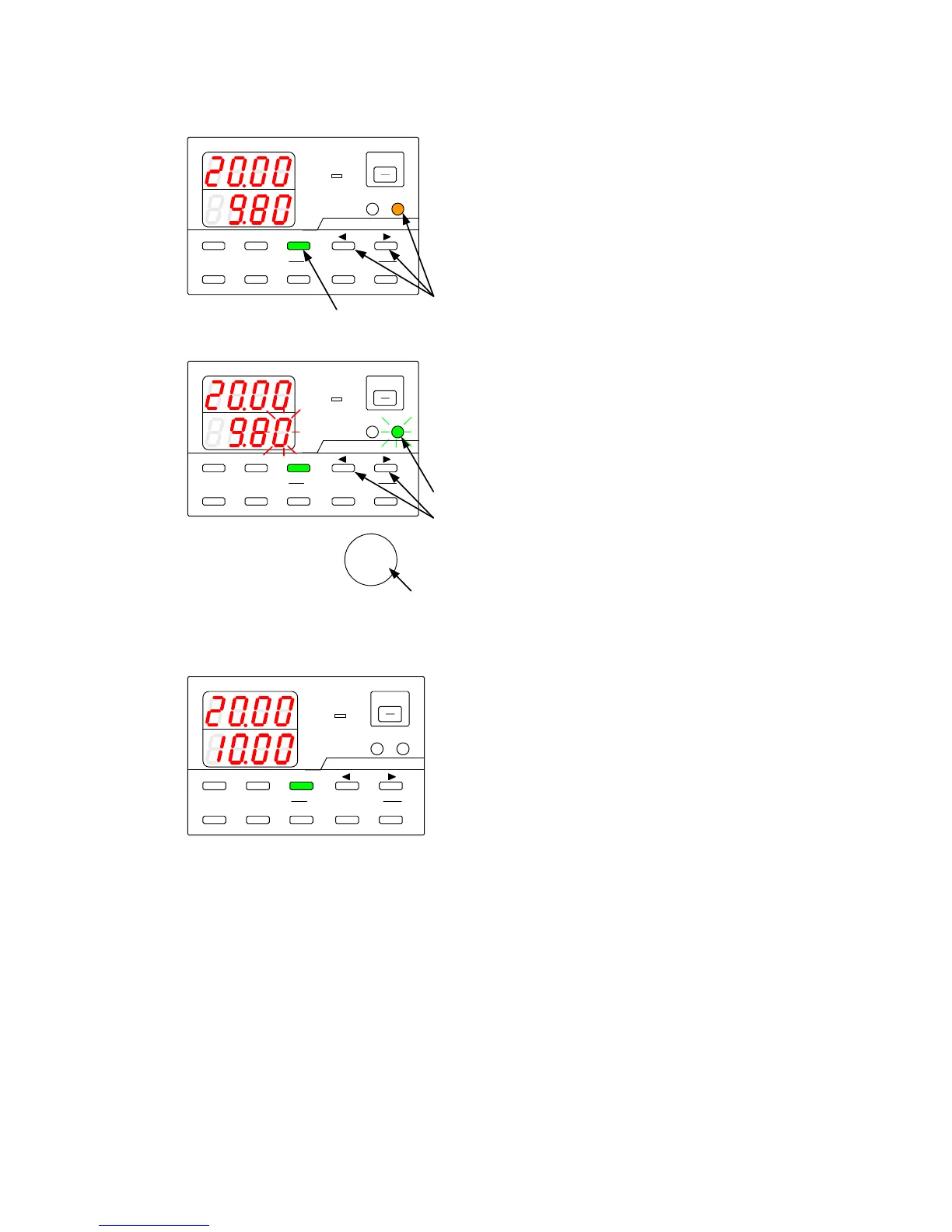
Press the CHECK key, which is then lit in green.
The current indicator displays the set current
value that corresponds to the external analog
signal.
Press the A key while pressing and holding one
of the DIGIT
▲
▼
keys.
The A key is then to lit in amber.
The current indicator displays the internally set
current.
A digit starts blinking in the current indicator.
Press the DIGIT
▲
▼
keys to move the
blinking digit in the current indicator.
Turn the rotary encoder to modify the internally
set current.
Press the A key.
The key then starts to blink green.
Press the green-blinking A key.
The light then goes out.
The blinking digit in the current indicator stops
blinking and then remains lit.