9-2-2. Adjusting the set voltage
Modify the internally set voltage to adjust the set voltage specified by the externally set voltage.
A
V
W
W
CC:R
CV:G
OUTPUT
V(W) A(W)
MENU PROTECT CHECK
ESC/ KEY LOCK ENTER/ MEM 1 2 3
DIGIT
PRESET/ SEQUENCE
* LOCK/ RMT STEP STOP PAUSE START
1
2
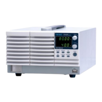
PDS-A series
A
V
W
W
CC:R
CV:G
OUTPUT
V(W) A(W)
MENU PROTECT CHECK
ESC/ KEY LOCK ENTER/MEM 1 2 3
DIGIT
PRESET/ SEQUENCE
* LOCK/ RMT STEP STOP PAUSE START
3
4
5 6
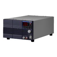
PDS-A series
A
V
W
W
CC:R
CV:G
OUTPUT
V(W) A(W)
MENU PROTECT CHECK
ESC/ KEY LOCK ENTER/ MEM 1 2 3
DIGIT
PRESET/ SEQUENCE
* LOCK/ RMT STEP STOP PAUSE START
PDS-A series
◆ See "9-2-1. Setting the Voltage” for details
about how to input the external analog signal
into the connector of the analog IF board.
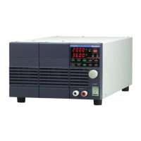
Press the CHECK key, which is then lit in green.
The voltage indicator displays the set value that
corresponds to the external analog signal.
Press the V key while pressing and holding one
of the DIGIT
▲
▼
keys.
The V key then is lit in amber.
A digit starts blinking in the voltage indicator.
The current indicator displays the value of the
internally set voltage.
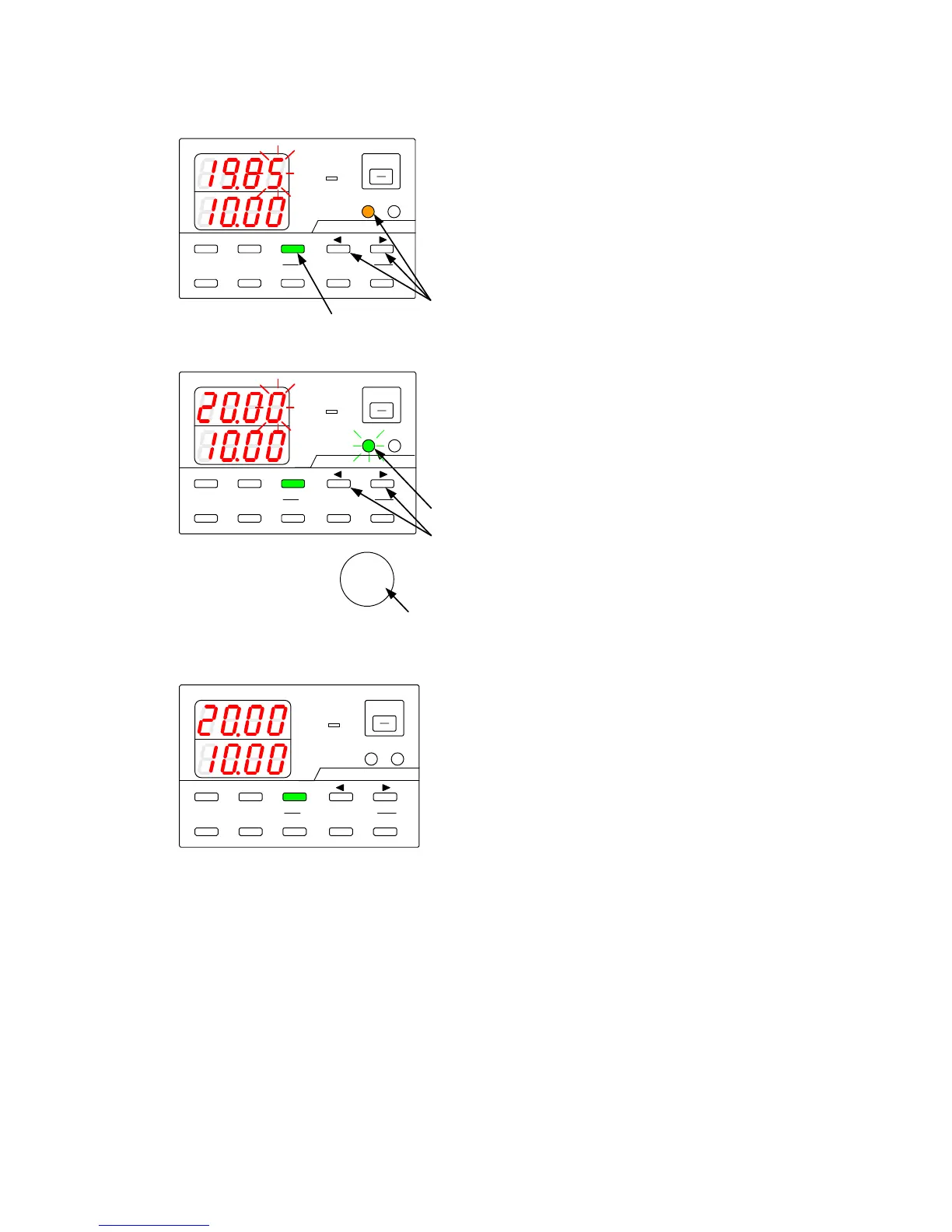
Press the DIGIT
▲
▼
keys to move the
blinking digit in the voltage indicator.
Turn the rotary encoder to modify the internally
set voltage.
Press the V key.
The key then starts to blink green.
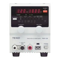
Press the green-blinking V key.
The light then goes out.
The blinking digit in the voltage indicator stops
blinking and then remains lit.