11. USING DIGITAL COMMUNICATION INTERFACE FOR REMOTE CONTROL
11-1. Outline
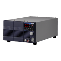
If a digital communication interface has been installed in place of the standard board, the PDS-A series unit can be
remotely controlled by a personal computer (hereinafter "PC") or sequencer via a USB, GP-IB, or RS-232C.
Because the digital communication interface has a local bus, a single PC or sequencer can control multiple PDS-A
series units.
The optional digital communication interface boards (referred as “digital IF board” hereinafter) for the PDS-A series are
as follows:
● IF-70GU: Used with GP-IB and USB digital communication interfaces. Can be connected to a PC for remote control.
● IF-71LU: Used with GP-IB and USB digital communication interfaces. Can be connected to a PC for remote control.
● IF-71RS: Used with communication interfaces that are compatible with RS-232C. Can be connected to a PC or
sequencer for remote control.
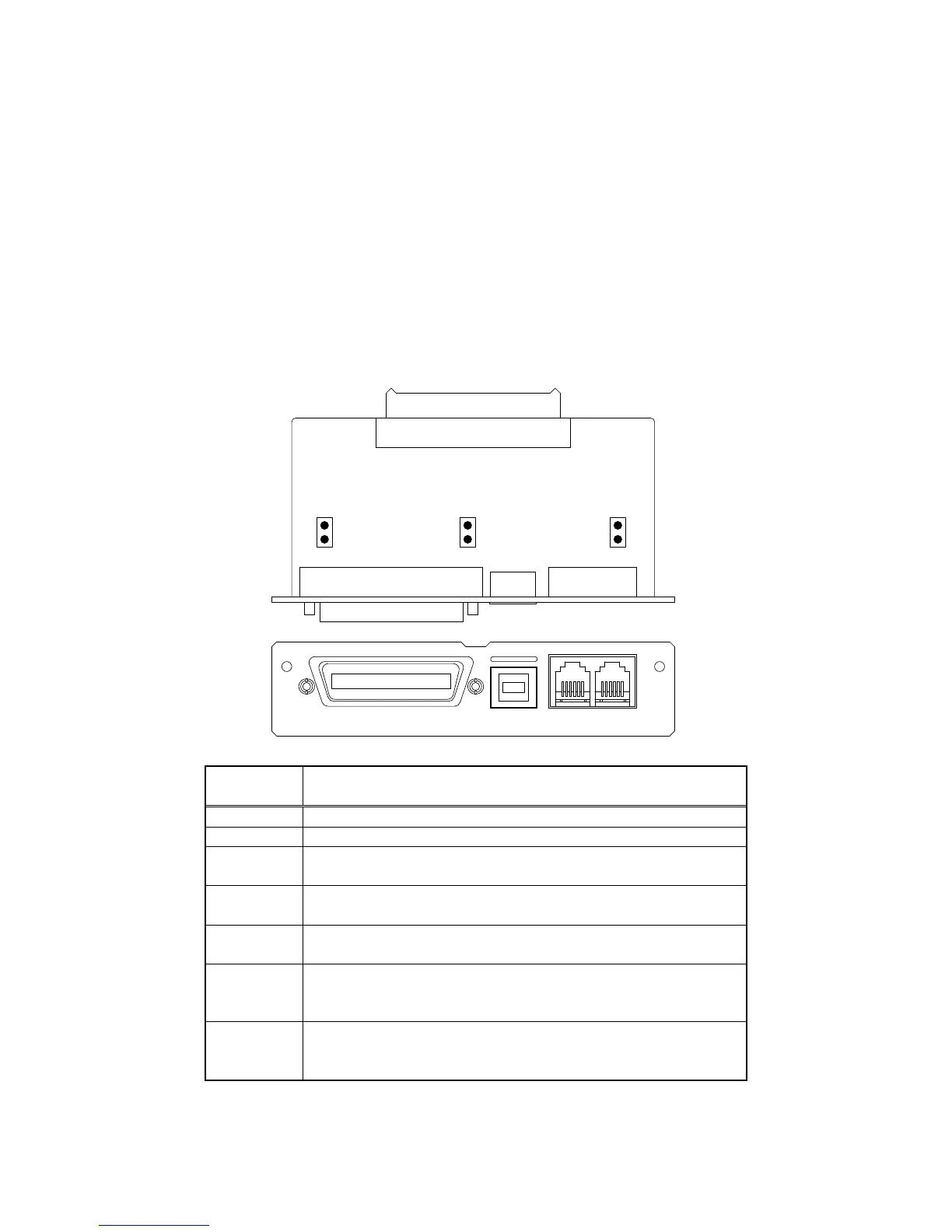
11-1-1. IF-70GU
LOCAL BUS
1 16 6
GP-IB
IF-70GU
CN2
CN4
CN3
CN1
USB
Connects to the GP-IB controller of PC.
Connects to the USB port of a PC or USB hub.
Connects to the local bus. A dedicated modular cable is required to
connect to the local bus.
Connects to the power unit. For details about how to connect to the power
unit, see the IF-70GU instruction manual.
Short-circuits the frame GND and signal GND of GP-IB and USB.
CN 2 is used to eliminate ground loops in noisy environments.
Connects to the terminator of the local bus and the internal bus when the
circuit is closed. In the local bus, a terminator is required for the power
supply units at each end of the signal line or for stand alone.
Switches operation between the GP-IB and USB.
The GP-IB operates when the circuit is closed, and the USB operates
when the circuit is open.


 To Next Page