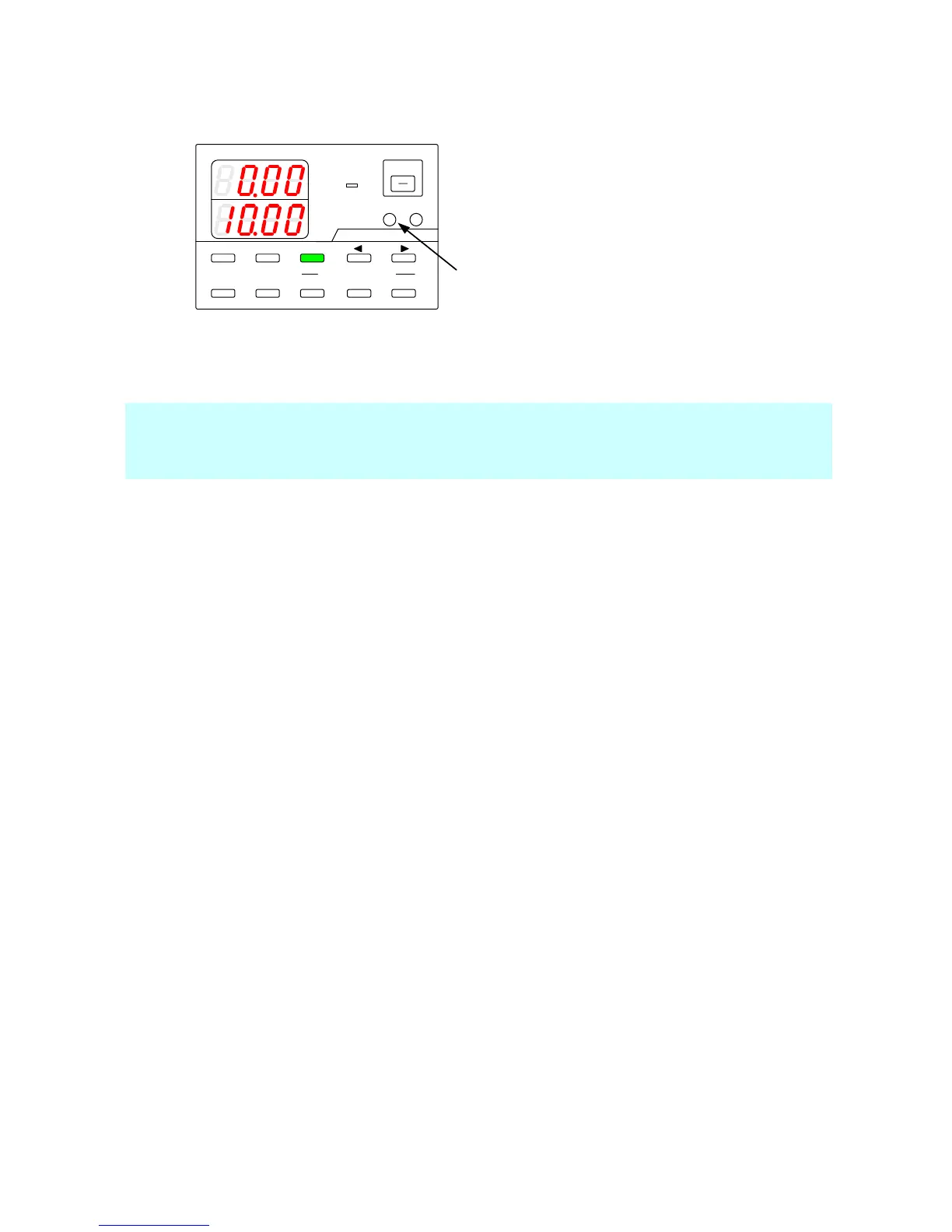
Press the green-blinking A key.
The light then goes out.
Input the external analog signal to the connector
on the analog IF board.
The current indicator displays the set value that
corresponds to the external analog signal.
The display range of the set current is from -10%
to +110% of the rated current.
The connector of the analog IF board varies
according to the type of external analog signal.
◆ For details, “9-1-2. Wiring an analog signal to
the standard board”
The current that can be set by performing this operation may exceed the maximum rated current of the unit, depending
on how it is used.
When the current is set lower than 0A or higher than 102.5% of the rated current, all the digits on the voltage indicator
will blink, and the output will be turned from on to off.