0V
10V
Rating
External voltage
Set voltage
0V
0V
10kΩ
External resistance
0Ω
Action Ⅰ
or
0V External resistance
0Ω 10kΩ
Action Ⅱ
Internally set voltage :0V Internally set voltage :rated voltage
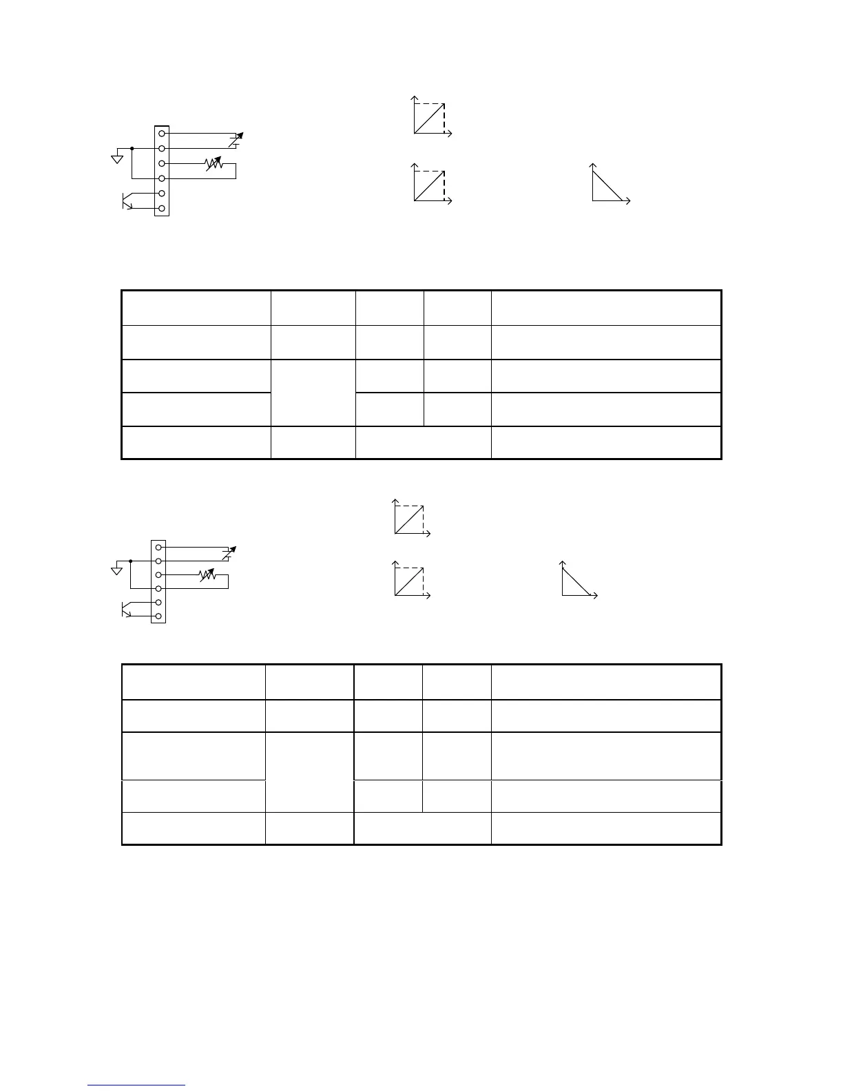
1
6
CN2
Set voltage modified
by external voltage
Set voltage modified
by external resistance
CV mode output
+
Rating
Set voltage
Set voltage
Rating
Set voltage control via external signa (Valid when pin No.4 of SW1 is on)
External voltage 0V → 10V
Set voltage 0V → Rated voltage
External resistance
control: Action I
External resistance 0Ω → 10kΩ
Set voltage 0V → Rated voltage
External resistance
control: Action II
External resistance 0Ω → 10kΩ
Set voltage: Rated voltage → 0V
Photo-coupler is on while in CV mode
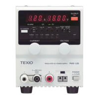
1
6
CN3
Set current control
via external voltage
Set current control via
external resistance
CC mode output
+
0V
10V
Rating
External voltage
Set current
0V
0V
10kΩ
Rating
External resistance
0Ω
Action Ⅰ
or
Set current
0V
Rating
External resistance
0Ω 10kΩ
Action Ⅱ
Internally set current :0A Internally set current : rated current
Set current
Set current control by external signal (Valid when pin No.7 of SW 1 is on)
External voltage 0V → 10V
Set current 0A → Rated current
External resistance
control: Action I
External resistance 0Ω → 10kΩ
Set current 0A → Rated
current
External resistance
control: Action II
External resistance 0Ω → 10kΩ
Set current: Rated current → 0A
Photo-coupler is on while in CC mode
◆ See “9-2-2. Adjusting the set voltage” and “9-2-3. Current setting” for details about how to set the internal voltage
and current.
If the standard board has been installed in the unit, the connectors (CN1, 2, 3), are arranged in the same way as shown in
the above figure.
The board features screwless connectors. Press the button of the connector and insert the cable (from which 10 mm
of the isolation coat has been stripped) into the hole on the left side of the button.
Use the AWG#24 - #28 cables (UL1007 stranded wire).