CUTMASTER 60i
Manual 0-5475 SERVICE
5-49
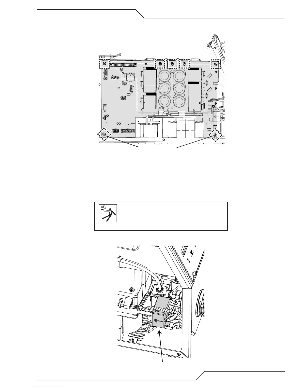
6. Everything should be disconnected from the Inverter PCB at this time. Next remove the five (5) nuts along
the top of the PCB and only loosen the two (2) in the bottom corners.
Loosen ONLY
Art # A-13324
7. Tip the top of the PCB toward you and lift it out.
Proedure is now complete.
HCT1 Current Sensor Removal
1. Remove the cover. See first step in subsection 5.12.
WARNING
Disconnect primary power to the system before
disassembling the torch, leads, or power supply.
2. Locate the HCT1, Current Sensor next to the ATC connector at the front of the unit.
HCT1
Art # A-13337