Manual 0-2568 11 INTRODUCTION & DESCRIPTION
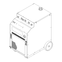
13. Power Supply Dimensions
Enclosure Only -
Width: 24.12 in (0.61 m)
Height: 38.38 in (0.98 m)
Depth: 34.25 in (0.87 m)
Fully Assembled -
Width: 28.50 in (0.72 m)
Height: 43.38 in (1.10 m)
Depth: 43.75 in (1.11 m)
14. Weight of Power Supply Only
678 lbs (308 kg)
2.04 Theory Of Operation
A. Plasma Arc Cutting and Gouging
Plasma is a gas which is heated to an extremely high tem-
perature and ionized so that it becomes electrically con-
ductive. The plasma arc cutting process uses this plasma
gas to transfer an electric arc to a workpiece. The metal
to be cut is melted by the intense heat of the arc and then
blown away by the flow of gas. Plasma arc gouging uses
the same process to remove material to a controlled depth
and width.
With a simple change of torch parts, the system can also
be used for plasma arc gouging. Plasma arc gouging is
used to remove material to a controlled depth and width.
B. Input and Output Power
The Power Supply accepts input voltages from 200 to
575V, 50 or 60 Hz, three-phase. Input voltages are set by
an internal changeover in the unit. The unit converts AC
input power to DC power for the main cutting arc. The
negative output is connected to the torch electrode
through the negative torch lead, and the positive output
connects to the workpiece through the work cable.
C. Pilot Arc
When the torch is activated there is a two second gas pre-
flow, followed by a uninterrupted DC pilot arc established
between the electrode and tip. The pilot arc is initiated
by a momentary high voltage pulse from the Arc Starter
Box. The pilot creates a path for the main arc to transfer
to the work. When the main arc is established, the pilot
arc shuts off. The pilot automatically restarts when the
main arc stops, as long as the torch remains activated.
NOTE
For the arc to restart automatically, AUTO RE-
START must be enabled at switch settings inside
the Power Supply (Refer to Section 4.07).
D. Main Cutting Arc
The Power Supply accepts 50 or 60 Hz three-phase line
input. An internal changeover switches input line volt-
ages in three ranges, for 200/220/230V, 380/415/460V,
or 500/575V operation. The power supply converts AC
input power to DC power for the main cutting arc. The
negative output is connected to the torch electrode
through the negative torch lead. The positive output is
connected to the workpiece via the work cable and ring
lug connection.
E. RF Shielding
All machine torch systems are shielded to minimize ra-
dio frequency (RF) interference which results from the
high frequency arc initiation. These shielded systems are
designed with features such as a wire for establishing an
earth ground and shielded torch and control leads.
F. Interlocks
The system has several built-in interlocks to provide safe
and efficient operation. When an interlock shuts down
the system, the fault condition must be remedied and the
system recycled using the applicable control device.
1. Parts-In-Place (PIP) Interlock
The Power Supply has a built-in parts-in-place inter-
lock that prevents accidental torch starting when torch
parts are not properly installed. A flow switch on the
coolant return lead detects reduced coolant flow
caused by improper torch assembly. If not satisfied,
the switch interrupts power to the tip and electrode.
2. Gas Pressure Interlock
A pressure switch acts as an interlock for the plasma
gas supply. If the supply pressure falls below mini-
mum requirements the pressure switch will open,
shutting off the power to the contactors, and the GAS
indicator will go out. When adequate supply pres-
sure is available the pressure switch will close, allow-
ing power to be resumed for cutting.
3. Thermal Interlock
Thermal overload sensors are located in the trans-
former, pilot resistors, and main heatsink in the power
supply. If one of these components is overheated the
appropriate switch will open, causing the tempera-
ture light to turn from green to red and shutting off

 Loading...


