INSTALLATION PROCEDURES 24 Manual 0-2568
NOTE
Refer to the Installation sections in the Maximizer
300 Torch Instruction Manual (0-2573) for more
information on the Torch.
3.12 External Cable Connections
Depending on the options installed there are various
cables to be connected the Power Supply.
A. Optional RC 6010 Remote Control
For mechanized systems, the optional RC 6010 Remote
Control allows the operator to control all system func-
tions from a remote location. The control cable to inter-
face the RC 6010 to the Power Supply is available in vari-
ous lengths (Refer to Section 6.04, Options and
Accessories).
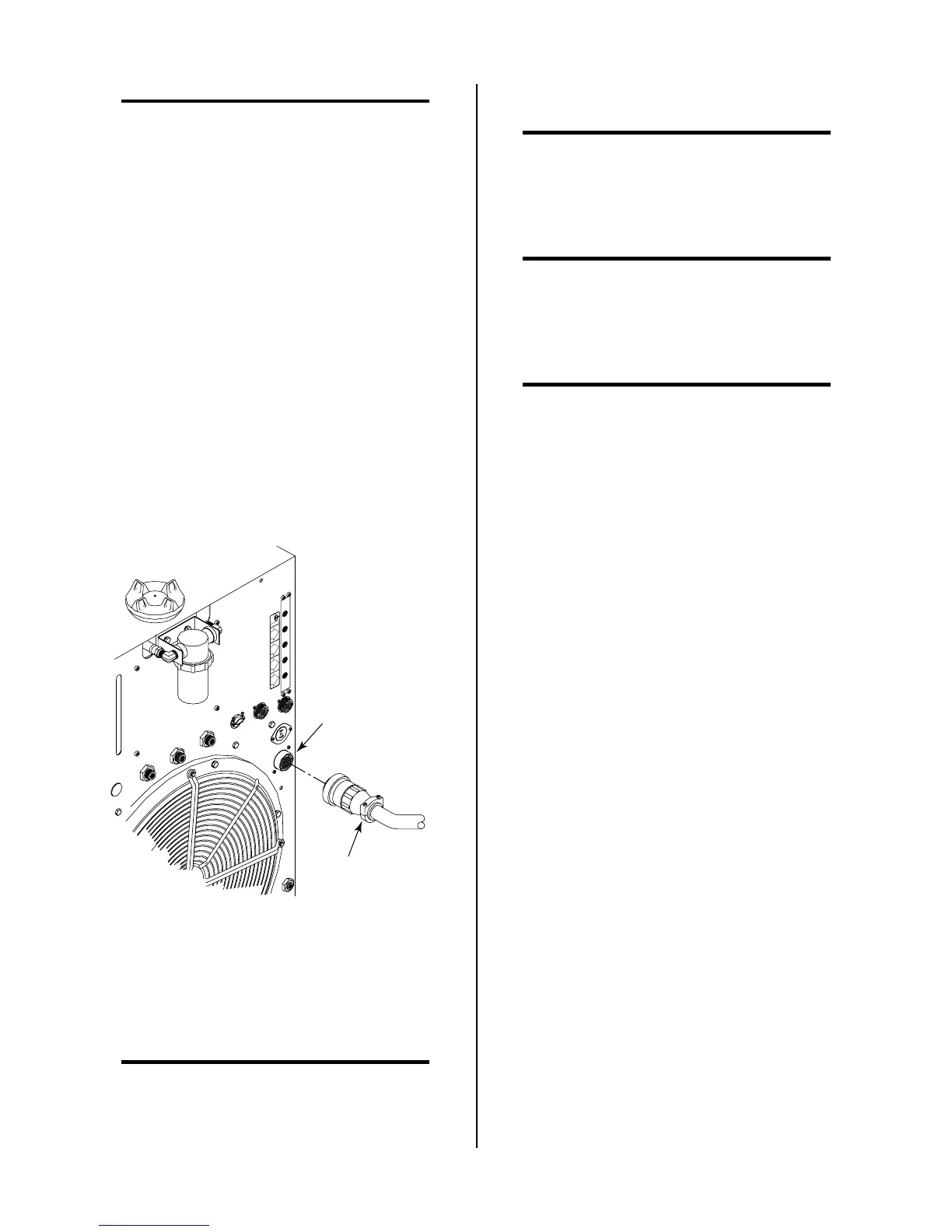
1. Connect the control cable to the receptacle marked
REMOTE CONTROL (J15) on the rear panel of the
Power Supply.
OUTPUT
TO
CONTROL
MODULEMODULE
AIR
PLASMAPLASMA
INPUTINPUT
N
2
PLASMAPLASMA
INPUTINPUT
O
2
PLASMAPLASMA
INPUTINPUT
PLASMA GASPLASMA GAS
Ar/H
2
PLASMAPLASMA
INPUTINPUT
A-01505
Cable From
Remote Control
REMOTE CONTROL
Connector (J15)
Figure 3-21 Remote Control Interface Connection
2. Connect the other end of the control cable to the
receptacle marked PS (J37) on the rear panel of the
remote control.
NOTE
Refer to the RC 6010 Remote Control Instruction
Manual 0-2478 for more information on the
RC6010 Remote Control including CNC.
B. Computer Control Interface (CNC)
NOTE
Used when Remote Control RC6010 or Standoff
Control SC11 are not used.
The computer control interface allows a mechanized sys-
tem to interface with a computer or other control device.
NOTE
Refer to Section 4.03-D for more information on
the CNC connections.
CNC cables can be interfaced to the Power Supply using
one of the following methods:
NOTE
Refer to Appendix VII for CNC Interface Sche-
matic.
• Connector (J15) at the rear of the Power Supply
• Internal terminal strip in the Power Supply
Depending on the equipment ordered and the cables sup-
plied connect the CNC cable per one of the following:
1. Using supplied CNC cable
Connect the supplied Power Supply/CNC Cable
to the Power Supply rear connector J15 labelled
REMOTE CONTROL.
2. Using customer supplied CNC Cable
a. Remove the Left Side Panel from the Power
Supply as viewed from the front of the unit.
b. Locate the internal terminal strip (TB2) near
the heatsink.
c. Feed the CNC cable through the small strain
relief at the rear of the Power Supply.
d. Connect the CNC cable to the terminal strip
(TB) per the following chart: