Manual 0-2568 25 INSTALLATION PROCEDURES
TB2
Connection
Description
1 One Side of Enable Signal (Comm on)
2 Other Side of Enable Signal (+15 vdc)
3
One Side of START(Low)/STOP
(High) Signal (+15 vdc)
4
Other Side of START (Low)/STOP
(High) Signal (Common)
5 Not Used
6 Not Used
7
One Side of Pilot Sensing Relay (PSR)
- Dry Contacts
8
Other Side of Pilot Sensing Relay
(PSR) - Dry Contacts
9
One Side of OK-To-M ove Signal
(Refer to Section 4.07)
10
Other Side of OK-To-Move Signal
(Refer to Section 4.07)
NOTES
Connections to TB2 positions 1 through 4 are acti-
vated with a switch or contact closure.
If Remote Control is not used the Enable Signal
circuit must be closed.
Connections TB2-7 and TB2-8 are normally open
(NO) contacts.
Connections TB2-9 and TB2-10 are selectable for
normally open (NO) contacts or 24 VAC.
e. Secure the CNC cable by tightening the two
screws on the strain relief.
f. Reinstall the Left Side Panel.
C. Optional SC-10 or SC11 Standoff Control
Cable
For mechanized systems, the Standoff Control automati-
cally finds height and maintains torch standoff with a high
speed torch lifter motor. The unit consists of a remote
operator's control, torch lifter motor, and all cables re-
quired for installation. It is ordered and shipped sepa-
rately. Refer to the SC-10 or SC11 Standoff Control In-
struction Manual for more information.
Depending on the Standoff Control to be used connect
the cable per one of the following:
• Standoff Control SC10 used with the Remote
Control RC6010
Connect the internal ribbon cable to the Remote
Control RC6010. Refer to the Standoff Control In-
struction Manual for more details.
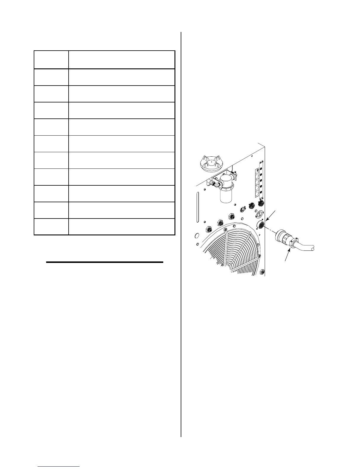
• Standoff SC11 only
The standoff control remote cable connects to the
receptacle marked REMOTE CONTROL (J15) on
the rear panel of the Power Supply.
A-01506
Cable From
Standoff Control
REMOTE CONTROL
Connector (J15)
OUTPUT
TO
CONTROL
MODULEMODULE
AIR
PLASMAPLASMA
INPUTINPUT
N
2
PLASMAPLASMA
INPUTINPUT
O
2
PLASMAPLASMA
INPUTINPUT
PLASMA GASPLASMA GAS
Ar/H
2
PLASMAPLASMA
INPUTINPUT
Figure 3-22 Standoff Control Interface Connection
D. Optional High-Flow Water Shield Cable
The High Flow Water Shield surrounds the main cutting
arc with a spray of water to reduce arc glare, noise, and
fumes. Use of the water shield device reduces the
system’s overall cutting capacity. Refer to the High-Flow
Water Shield Instruction Manual for more information.
1. Connect the high flow water shield interface cable
to the receptacle marked HIGH FLOW WATER
SHIELD on the rear panel of the Power Supply.
The receptacle is 115VAC.