Manual 0-2568 17 INSTALLATION PROCEDURES
tem is designed with to help prevent this problem. To
further minimize RF interference, follow these ground-
ing procedures when installing mechanized systems:
B. Creating an Earth Ground
1. Install a ground wire (not included) between the input
power line ground of the Power Supply (chassis) to a
solid earth ground (also called star ground). To cre-
ate a solid earth ground, drive a 1/2 in (12 mm) di-
ameter copper rod approximately 6 - 8 ft (1.8 - 2.4 m)
into the earth so that the rod contacts moist soil over
most of its length. The required depth will vary de-
pending on location. Locate the rod as close as pos-
sible to the power supply. The work table should be
connected to the same earth ground as the power sup-
ply.
2. Connect the control device (CNC) to a separate earth
ground similar to the ground rod described above.
The ground cable should be at least 12 gauge wire.
3. To minimize RF interference, position torch leads as
far as possible (at least 1 ft or 0.3 m) from any CNC
components, drive motors, control cables, or primary
power lines.
4. Keep torch leads clean. Dirt and metal particles bleed
off energy, which causes difficult starting and in-
creased chance of RF interference.
5. Make sure all ground cables are properly connected.
6. The work cable must have a solid connection to the
workpiece or cutting table. The connection must be
free from dirt, grease, oil and paint.
3.10 Plasma And Secondary Gas
Connections
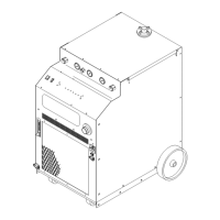
The Master Power Supply provides the liquid cooling and
gases to support operation of the Liquid Cooled Maxi-
mizer 300 Torch.
NOTE
Refer to the Liquid Cooled Maximizer 300 Torch
Instruction Manual (Cat. No. 0-2573 for informa-
tion on plasma and secondary gas selection and
requirements.
The following are available gases that can be used with
the Liquid Cooled Maximizer 300 Torch:
Plasma Gases: Compressed Air, Oxygen (O2), Nitro-
gen (N2), or Argon/Hydrogen (Ar/H2)
Secondary Gases: Compressed Air, Nitrogen (N2),
Carbon Dioxide (CO2), or Tap Water (refer to follow-
ing note)
Plasma and secondary requirements vary depending on
the application. The plasma and secondary gases are
connected to the rear panel connections of the power sup-
ply. Depending on the options installed and the source
of the gases will determine the installation of filters and
regulators.
This sub-section includes information for connecting the
gas supplies to the Power Supply. The information is
grouped in paragraphs for different types of gases and
options per the following:
A. Using Shop Air
B. Using High-Pressure Gas Cylinders
C. Using Water Secondary
D. Plasma and Secondary Gases With Gas Control
Option
Refer to the appropriate paragraph(s) for the desired ap-
plication to be used.
A. Using Shop Air
An inline pneumatic dryer/evaporator type air filter, ca-
pable of filtering particulates to at least 5 microns with a
dew point of 35°F (1.7°C), is required when using air from
a compressor. This type filter will insure that moisture,
oil, dirt, chips, rust particles, and other contminants from
the supply hose do not enter the torch. For highly auto-
mated applications, a refrigerated drier plus a particu-
late filter may be used to chill the air to remove all mois-
ture.
CAUTION
Excessive oil or moisture in compressed air will
reduce torch parts life and cutting performance and
may cause torch failure.
The optional Two Stage Air Line Filter is shipped with
the following components:
NOTE
The Two Stage Air Line Filter Assembly is to be
used when using shop air as the Plasma Gas.
• Installation Instructions - 1 each
• 10-32 Nylon Lock Nuts - 2 each
• Filter Mounting Bracket - 1 each
• Air Line Filter Assembly - 1 each
• 1/4 NPT Sreet Elbow - 1 each
• Thread Sealer - 1 each
• Filter To Plasma Gas Hose Assembly - 1 each (see
NOTE)
• Filter to Gas Option Hose Assembly - 1 each (see
NOTE)

 Loading...


