Manual 0-2568 47 CUSTOMER/OPERATOR SERVICE
N. No pilot; PILOT indicator ON; Strong spark
visible at spark gap points in Arc Starter Box
1. Faulty torch parts
a. Repair per Torch Manual
2. Faulty power supply
a. Isolate and replace component(s) per Service
Manual.
O. Pilot arc ON; No main arc transfer (torch brought
within range of work)
1. Work cable not connected
a. Connect work cable securely
2. Faulty power supply
a. Isolate and replace component(s) per Service
Manual.
P. System cuts at one-half expected current
1. Work cable not connected
a. Check work cable connection from Master
Power Supply. If using Slave Power Supply,
work cable must also be connected.
2. Slave Power Supply not ON
a. Turn ON front panel ON/OFF power switch
3. Parallel Cable not connected
a. Install Parallel Cable between Master and Slave
Power Supplies
Q. Slave Power Supply AC Power Indicator on Front
Panel not ON; Fan OFF
1. Customer’s main power disconnect is turned OFF
a. Turn ON main power disconnect
2. Front Panel ON/OFF switch is turned OFF
a. Turn ON front panel power switch
3. No primary power
a. Check for proper three-phase power at input
terminal board
4. Blown fuse (F2)
a. Check and replace fuse if necessary
5. Faulty power supply
a. Isolate and replace component(s) per Service
Manual.
5.05 Basic Parts Replacement
NOTE
For more detailed Parts Replacement Procedures
and Replacement Parts refer to Power Supply Ser-
vice Manual 0-2569.
The parts replacement procedures described in this
manual are for basic replacement of parts that requires
limited disassembly of the Power Supply.
WARNING
Disconnect primary power from the source before
disassembling the power supply.
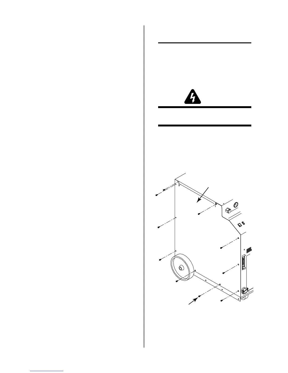
A. Side Panel Removal
The replacement of the fuse and filter assemblies can be
made through the left and right sides of the Power Sup-
ply. Remove the Right and Left Side Panels as follows:
1. Locate the removable Left and Right Side Panel of
the Supply as viewed from the front of the unit.
Left Side Panel
Screws
(10 Places)
A-01535
Figure 5-3 Side Panel Screw Removal
2. Remove the ten screws that secure each side panel
to the Power Supply.
3. Remove the side panels from the Power Supply.

 Loading...


