Manual 0-2568 9 INTRODUCTION & DESCRIPTION
SECTION 2:
INTRODUCTION &
DESCRIPTION
2.01 Scope of Manual
This manual contains descriptions, operating instructions
and basic maintenance procedures for the Merlin 6000
Plasma Cutting Master Power Supply. Service of this
equipment is restricted to Thermal Dynamics trained per-
sonnel; unqualified personnel are strictly cautioned
against attempting repairs or adjustments not covered in
this manual, at the risk of voiding the Warranty.
Read this manual thoroughly. A complete understand-
ing of the characteristics and capabilities of this equip-
ment will assure the dependable operation for which it
was designed.
2.02 General Description
The Master Power Supply contains all operator controls,
electrical and gas inputs and outputs, and the torch leads
receptacle. A Slave Power Supply may be connected in
parallel to double the the cutting capacity (amperage) of
the Master Power Supply. All signal inputs/outputs, gas,
and torch connections are still connected to the Master
Power Supply when the Slave Power Supply is used. The
Slave Power Supply has the same power circuits as the
Master Power Supply. The Master Power Supply can also
be connected to a second Master Power Supply and the
equipment will automatically be configured when the
parallel cable is installed. Many options and accessories
can be added to further improve the versatility of the
system.
NOTES
Refer to the Merlin 6000 Plasma Cutting Slave
Power Supply Operating Manual 0-2570 for more
information on the Slave Power Supply.
The Merlin 6000 Slave Power Supply requires a
Merlin 6000 Master Power Supply for proper op-
eration and torch connections.
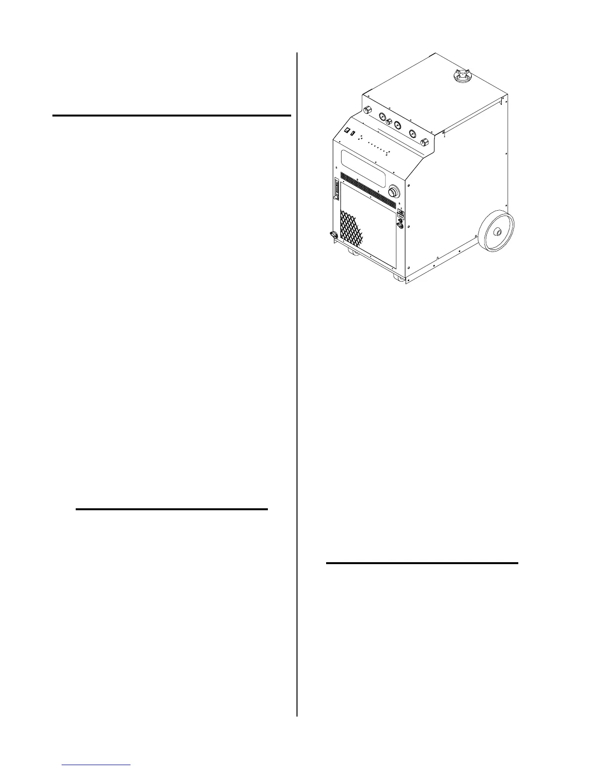
A-01497
Figure 2-1 Power Supply
The Standard Coolant supplied with the Power Supply
can be used in ambient temperatures down to 10° F
(-12° C). If the ambient temperature will be below 10° F
(-12° C) then Super Coolant should be used. This coolant
can be used in areas where the ambient temperature drops
to -34° F (-36° C).
A typical system configuration will contain the follow-
ing:
• One or two Power Supplies with Running Gear
• Arc Starter Box
• Maximizer 300 Machine Torch with Leads and
Mounting Assembly
• Torch Supply Leads
• Maximizer 300 Spare Parts Kit
• 25 ft (7.6 m) Work Cable and Ring Lug
• Optional Air Line Filter Assembly (or) High Pres-
sure Regulators
NOTE
Refer to Section 2.05 for complete list of Power
Supply Options and Accessories.