Home
Thermal Dynamics
Welding System
MERLIN 6000
Thermal Dynamics MERLIN 6000 User Manual
4
of 1
of 1 rating
74 pages
Give review
Manual
Specs
To Next Page
To Next Page
To Previous Page
To Previous Page
Loading...
P
ARTS LISTS
50
Manual
0-2568
6.03 Complete P
ower Supply Replacement P
ar
ts List
Qty
.
Description
Catalog #
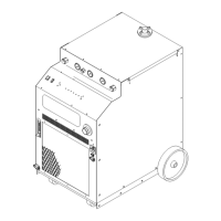
Merlin 6000 Master Power Supply (with Running Gear and W
ork Cable)
1
W
ithout Gas Control
3-6800
1
W
ith Gas Control
3-6802
1
W
ork Cable with Ring Lug - 25 ft (7.6 m)
9-6892
53
55
Table of Contents
Table of Contents
3
General Information
5
Notes, Cautions and Warnings
5
Important Safety Precautions
5
Publications
6
Note, Attention Et Avertissement
7
Precautions de Securite Importantes
7
Documents de Reference
9
Declaration of Conformity
11
Statement of Warranty
12
Introduction & Description
13
Scope of Manual
13
General Description
13
Specifications & Design Features
14
Theory of Operation
15
Options and Accessories
16
Installation Procedures
17
Introduction
17
Site Location
17
Unpacking
17
Removing Skid
17
Section 3 Installation Procedures
17
Filling Master Power Supply Coolant
18
Input Power Connections
18
Voltage Selection
19
Primary Power Cable Connections
20
Work Cable and Ground Connections
20
Plasma and Secondary Gas Connections
21
Connecting Torch Supply Leads
26
External Cable Connections
28
Master/Slave Parallel Cable Connection
30
Lifting Options
30
Pilot Resistor Adjustment
31
Operation
35
Introduction
35
Operation Section
35
Functional Overview
35
Front and Rear Panel Descriptions
35
Operating Unit Without Gas Control Option
38
Operating Unit with Gas Control Option
40
System Operation
41
Optional Power Supply Settings
42
Customer/Operator Service
47
Introduction
47
General Maintenance
47
Common Operating Faults
48
Troubleshooting
48
Basic Parts Replacement
51
Parts Lists
53
Introduction
53
Ordering Information
53
Complete Power Supply Replacement Parts List
54
Basic Component Replacement Parts List
55
Power Supply Options and Accessories
56
Appendix I: Input Wiring Requirements
57
Appendix II: Sequence of Operation Block Diagram
58
Appendix III: Typical Mechanized System Work and Ground Cable Connections
59
Appendix IV: Typical Mechanized System Cable Interconnection Diagram
60
Appendix V: Quick Reference to Interconnecting Cables and Hoses
62
Appendix VI: Interface Cable for Remote Control (Rc6010)
63
Appendix VII: Interface Cable for Standoff Control (Sc11)
64
Appendix VIII: Cnc Interface Cables
65
Appendix IX: Ladder Diagram - 120 Vac
66
Appendix X: Ladder Diagram - 15 VDC
67
Appendix XI: Parallel Cable
68
Appendix XII: Recommended Routine Maintenance Schedule for Water Cooled Plasma Cutting Systems
69
APPENDIX XIII: SYSTEM SCHEMATIC - Rev 'B' or Earlier
70
APPENDIX XIV: SYSTEM SCHEMATIC - Rev 'C' or Later
72
Other manuals for Thermal Dynamics MERLIN 6000
Service Manual
112 pages
4
Based on 1 rating
Ask a question
Give review
Questions and Answers:
Need help?
Do you have a question about the Thermal Dynamics MERLIN 6000 and is the answer not in the manual?
Ask a question
Thermal Dynamics MERLIN 6000 Specifications
General
Brand
Thermal Dynamics
Model
MERLIN 6000
Category
Welding System
Language
English
Related product manuals
Thermal Dynamics Pak Master 25
50 pages
Pak Master 100XL
44 pages
PAK Master 150XL
60 pages
PAK Master 100XL Plus
52 pages
Thermal Dynamics CUTMASTER
82 pages
Thermal Dynamics 51 CUTMASTER
60 pages
Thermal Dynamics CUTMASTER 39
82 pages
Thermal Dynamics 152 CUTMASTER
84 pages
Thermal Dynamics CUTMASTER 151
172 pages
Thermal Dynamics CUTMASTER A120
128 pages
CE CutMaster 80XL
46 pages
ULTRA-CUT 200 XTâ„¢
228 pages