Manual 0-2568 27 INSTALLATION PROCEDURES
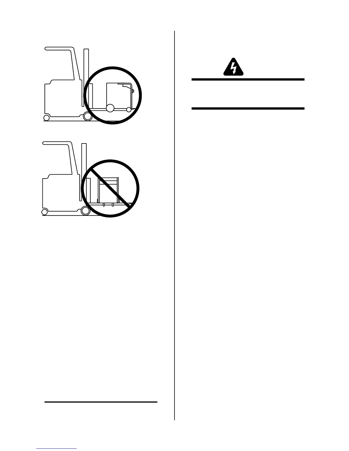
3. Center the forks under the unit and carefully check
for proper balance before lifting.
Approach From Front Or Rear
Do Not Lift From Sides
A-01499
Figure 3-25 Lifting the Power Supply
3.15 Pilot Resistor Adjustment
This Sub-Section applies only to the following Master and
Slave Power Supplies:
• Merlin 6000 Master Power Supplies with the revi-
sion letter 'C' or later at the end of the serial num-
ber on the data tag
• Slave Power Supplies with the revision letter 'E' or
later at the end of the serial number on the data tag
• Slave Power Supplies that have been retrofitted with
Pilot Resistors
Master and Slave Power Supplies, as noted above, con-
tain adjustable pilot resistor circuits. For output current
below 250A, only the pilot circuit in the Master Power
Supply is activated. For output current above 250A the
Master and Slave Power Supply pilot circuits are acti-
vated.
Master and Slave Power Supply pilot resistors are ini-
tially set at the factory and may need to be adjusted to
the customer's input power (see Notes).
NOTES
The instructions in this Sub-Section apply to the
Master Power Supply only.
To adjust the Slave Power Supply pilot resistor,
refer to the Manual supplied with the Slave Power
Supply.
WARNING
Disconnect primary power at the source before as-
sembling or disassembling power supply, torch
parts, or torch and leads assemblies.
The pilot current consists of two parts:
1) Minimum or “background” level
2) Pulse or peak level
The background level has to be high enough that the pi-
lot will not sputter or go out, but not too high to cause
excessive wear of the torch consumables. Adding pulses
of current on top of the background current allows greater
arc transfer distance without increasing the torch part
wear. The amount of pilot current is determined by the
value of the pilot resistors and the open circuit voltage
which varies with the input line voltage. Both the Mas-
ter and the Slave Power Supplies should be adjusted the
same. Wire #99 tap sets the background level and wire
#150 tap sets the pulse level. To set the pilot background
and pulse levels use the following procedure:
1. Remove the left and right side panels of the Master
Power Supply.
2. Locate and identify the pilot resistors (R16, R21
and R22) which are on a bracket in front of the
fan.