INSTALLATION PROCEDURES 26 Manual 0-2568
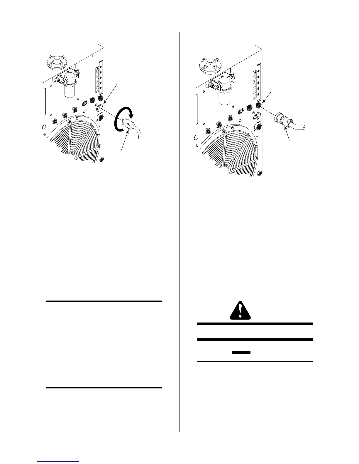
High Flow Water Shield
Interface Cable
High Flow Water Shield
Connector (J63)
Rotate Clockwise
To Lock
A-01507
OUTPUTOUTPUT
TOTO
CONTROLCONTROL
MODULE
AIRAIR
PLASMA
INPUT
N
2
PLASMA
INPUT
O
2
PLASMA
INPUT
PLASMA GASPLASMA GAS
Ar/HAr/H
2
PLASMA
INPUT
Figure 3-23 High Flow Water Shield Interface
Connection
2. Rotate the plug clockwise to lock the plug to the
receptacle.
3. To shut off the high flow water shield remove the
interface cable or disconnect power to the High
Flow Water Shield (HFWS) accessory.
E. Optional Gas Control Connection
The optional GS3000 Gas Control allows the connection
of various multiple plasma and secondary gases to be
connected to the Power Supply. The proper plasma and
secondary gas is selected with switches on the front panel
of the Gas Control Option.
NOTE
The secondary selection switch on the front panel
of the Power Supply must always be set to GAS
for all secondary gases when the Gas Control Op-
tion is installed.
1. Connect the Gas Control control cable to the con-
nector marked GAS CONTROL (J63) on the rear
panel of the Power Supply.
2. Connect the other end of the cable to the Gas Con-
trol Option rear panel.
NOTE
Refer to the Gas Control Instruction Manual 0-
2477 for more information on the GS3000 Gas
Control Option.
Cable From
Gas Select Option
GAS CONTROL
Connector (J63)
A-01508
OUTPUT
TO
CONTROL
MODULEMODULE
AIRAIR
PLASMAPLASMA
INPUTINPUT
N
2
PLASMAPLASMA
INPUTINPUT
O
2
PLASMAPLASMA
INPUTINPUT
PLASMA GASPLASMA GAS
Ar/HAr/H
2
PLASMAPLASMA
INPUTINPUT
Figure 3-24 Optional Gas Control Interface
Connection
3.13 Master/Slave Parallel Cable
Connection
The interface between the Master and Slave Power Sup-
ply is made through the Parallel Cable. Connect one end
of the cable to the rear of the Master Power Supply at J54.
The other end connects to the rear of the Slave Power
Supply at J15.
3.14 Lifting Options
WARNING
Do not lift the power supply by the handles.
CAUTION
Do not lift a power supply equipped with a cylin-
der rack running gear.
The recommended method for lifting the power supply
is to use a forklift per the following procedure:
1. Approach from the front or rear of the unit.
2. Place the forks between the rear wheels or the front
casters.

 Loading...


