INSTALLATION PROCEDURES 16 Manual 0-2568
200, 208,
220, or 230
11
12
L3
13
15
14
6
7
L2
8
10
9
1
2
L1
3
5
4
380, 415,
or 460
11
12
L3
13
15
14
6
7
L2
8
10
9
1
2
L1
3
5
4
500, or 575
11
12
L3
13
15
14
6
7
L2
8
10
9
1
2
L1
3
5
4
Busbar Connections For Input Voltages
A-00904
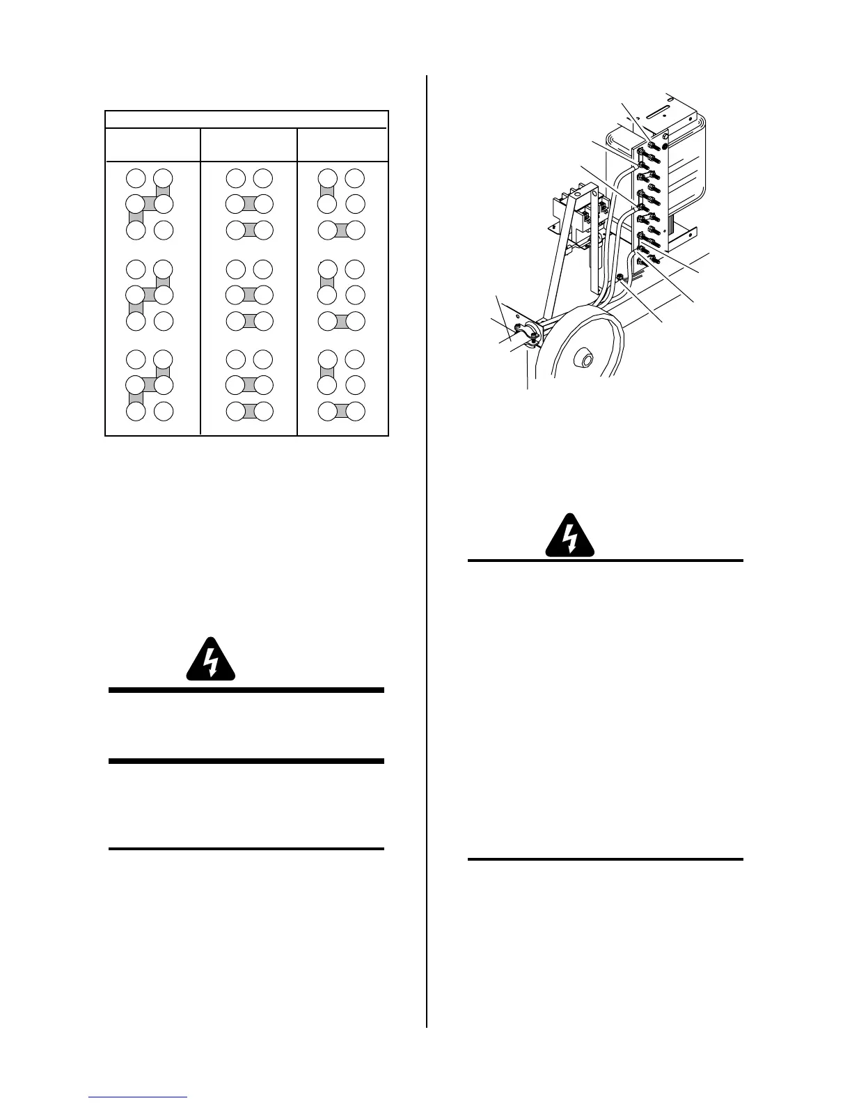
Figure 3-5 Busbar Connections
If necessary, reposition the busbars to correspond to
the available line voltage.
3.08 Primary Power Cable
Connections
WARNING
Disconnect primary power at the source before con-
necting the primary power cable to the power sup-
ply.
The primary power cable must be supplied by the end
user and installed to the Power Supply assembly. Rec-
ommended cable sizes are specified in Appendix I.
NOTE
Three-phase operation requires a 3-conductor cable
with ground.
1. Route the primary power cable through the strain
relief fitting in the rear panel of the Power Supply
and tighten strain relief screws.
Input Voltage
Terminal Board
L1
L2
L3
Primary Power
Cable
Strain Relief
Fitting
Ground
Connection
Busbars
A-00893
Figure 3-6 Input Voltage Connections
2. Connect the electrical ground wire to the ground
lug on the base of the unit.
WARNING
The electrical ground wire must be connected to
the ground lug in the base of the unit for proper
grounding.
3. Connect the three line leads to the input voltage
terminal board per the following:
• Line 1 to terminal L1.
• Line 2 to terminal L2.
• Line 3 to terminal L3.
4. Tighten all nuts.
3.09 Work Cable And Ground
Connections
NOTE
Refer to Appendix III for a block diagram of a typi-
cal mechanized system work and ground cable con-
nections.
A. Electromagnetic Interference (EMI)
High frequency pilot arc initiation generates a certain
amount of electromagnetic interference (EMI), commonly
called RF noise. This RF may interfere with other elec-
tronic equipment such as CNC controllers, etc. The sys-