INSTALLATION PROCEDURES 18 Manual 0-2568
NOTE
Only one of these will be used depending on con-
figuration of Power Supply.
Install the Two Stage Air Filter Kit as follows:
NOTE
Use these instructions only for Power Supplies that
DO NOT have the Gas Control Option installed.
1. Remove the air supply input hose from the Plasma
Gas (Air) Input Fitting at the rear of the power sup-
ply, if already installed.
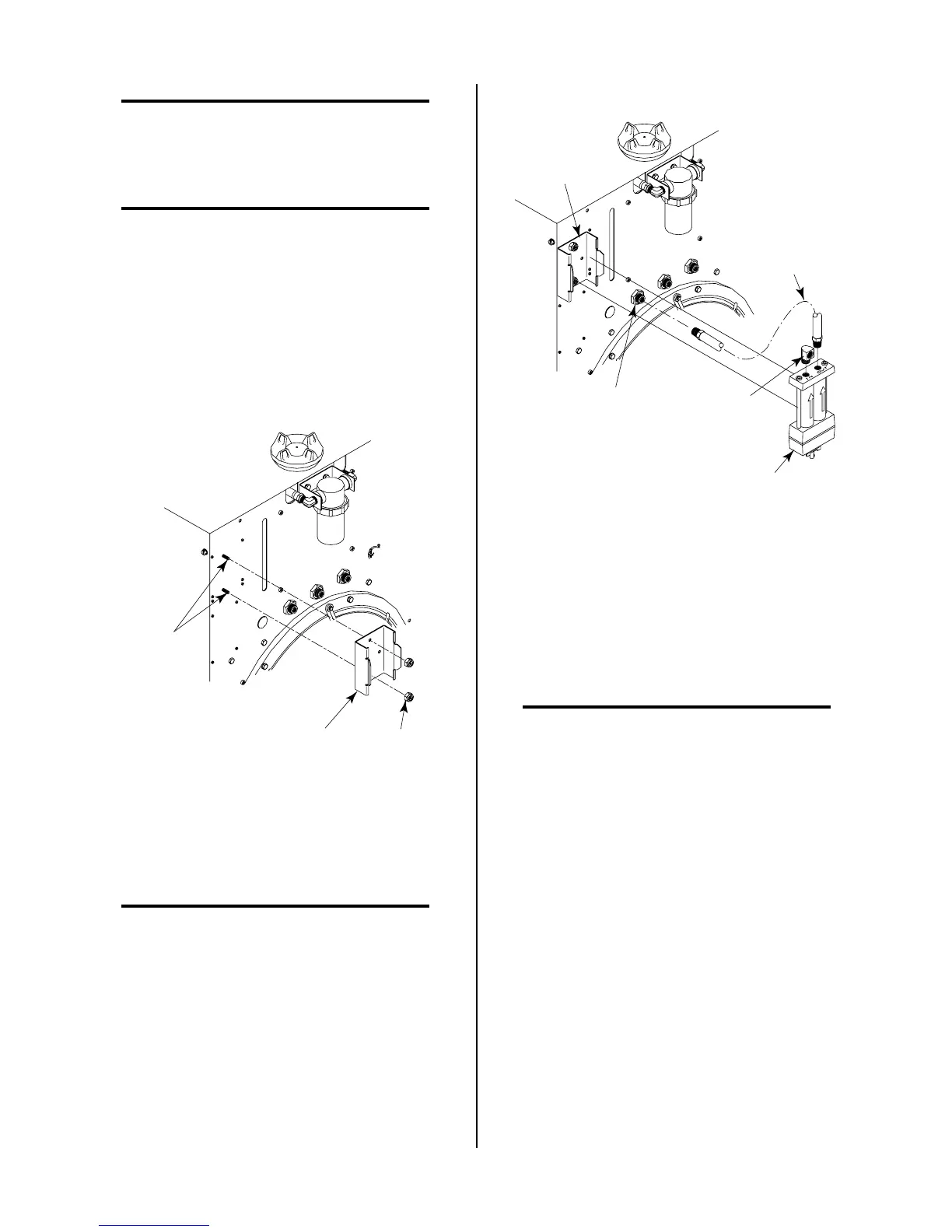
2. Locate the two mounting studs on the rear of the unit
and secure the Air Filter Mounting Bracket to the panel
using the two 10-32 Nylon Locking Nuts provided.
Air Filter
Mounting Bracket
Mounting
Nuts
Mounting
Studs
A-01336
Figure 3-7 Air Filter Mounting Bracket Installation
3. Place thread sealer on the threads of the 1/4 NPT Street
Elbow (see NOTE).
NOTE
Do Not use teflon tape as a thread sealer as small
particles of the tape may break off and cause the
small gas passage to be blocked in the torch.
4. Install the supplied 1/4 NPT Street Elbow into the
input port (IN) of the Air Line Filter Assembly.
5. Slide the Air Line Filter Assembly into the mounting
bracket. The Filter Assembly will snap into place.
A-01337
Hose Assembly
Filter to Plasma
Gas Input
1/4 NPT
Elbow
Filter
Assembly
Air Filter
Mounting Bracket
Plasma Gas
Input Fitting
Figure 3-8 Two Stage Air Line Filter Installation
6. Using the Filter to Plasma Gas Hose Assembly con-
nect the output port (OUT) of the Air Line Filter As-
sembly to the Plasma Gas Input Fitting.
7. Place thread sealer on the threads of the Street Elbow
on a Y-Hose Assembly (see NOTES).
NOTES
Do Not use teflon tape as a thread sealer as small
particles of the tape may break off and cause the
small gas passage to be blocked in the torch.
The Y-Hose Assembly is customer supplied and is
shown to illustrate one method of connecting the
customer's air supply.
8. Connect the air supply hose from a Y-Hose Assembly
to the street elbow on the Air Line Filter input port
(IN). The Y-Hose Assembly should have already been
installed, if shop air was being used as the plasma
and secondary gases.