Manual 0-2568 19 INSTALLATION PROCEDURES
A-01338
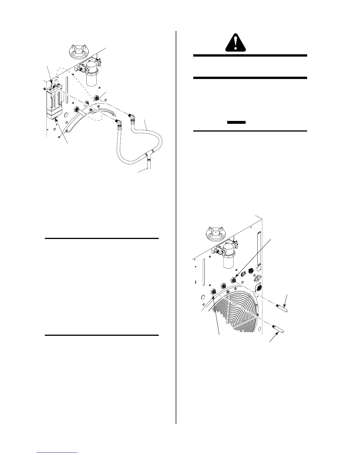
Shop Air
Gas Input
Air Filter
Assembly
Secondary Air
Gas Fitting
Y-Hose
Assembly
From Supply
Figure 3-9 Supply Hose Connections Witout Gas
Control Option
9. Apply thread sealer (see NOTE) to the other elbow of
the Y-Hose Assembly.
NOTE
Do Not use teflon tape as a thread sealer as small
particles of the tape may break off and cause the
small gas passage to be blocked in the torch.
10. Connect the elbow fitting to the SECONDARY (Air)
1/4 NPT fitting.
11. Connect the supply line from the air supply source to
the Y-hose assembly. The supply hose must be 3/8 in
(10 mm) minimum inside diameter to provide ad-
equate air flow.
B. Using High-Pressure Gas Cylinders
NOTES
Refer to the regulator manufacturer’s specifications
for installation and maintenance procedures. Re-
fer to Section 6.05, System Options and Accesso-
ries, or a listing of available high-pressure regula-
tors.
Do not use an air line filter with high pressure gas
cylinders.
1. Examine the cylinder valves to be sure they are clean
and free of oil, grease or any foreign material. Mo-
mentarily open each cylinder valve to blow out any
dust which may be present.
WARNING
Do not stand in front of the valve outlet when open-
ing.
2. Each cylinder must be equipped with an adjustable
high-pressure regulator capable of pressures up to 125
psi (8.6 BAR) maximum and flows of up to 700 scfh
(328 lpm) for cutting or gouging.
CAUTION
Maximum input pressure to the internal regula-
tor on the Power Supply must not exceed 125 psi
(8.6 BAR).
Connect the gas supply to the Power Supply per the fol-
lowing:
1. Connect the black supply hose from the plasma
gas regulator directly to the input fitting on the
rear panel of the Power Supply marked PLASMA.
Plasma Gas
Supply Hose
Secondary Gas
Supply Hose
Secondary Gas
Fitting
Plasma Gas
Fitting
A-01503
Figure 3-10 Gas Connections Using Gas Cylinders
2. Connect the yellow supply hose from the second-
ary gas regulator directly to the input fitting on
the rear panel of the Power Supply marked SEC-
ONDARY. Do not use the air line filter with high
pressure cylinders.