INSTALLATION PROCEDURES 20 Manual 0-2568
NOTE
A typical 50 lb. CO2 cylinder can deliver a con-
tinuous flow rate of 35 scfh (16.5 lpm). To obtain
the required flow rate for the torch, it may be nec-
essary to manifold several CO2 cylinders. Con-
tinuous flow requirements will depend on the spe-
cific application and duty cycle.
C. Using Water Secondary
NOTES
Tap water should only be used as a secondary gas
on machine torches.
The tap water source does not need to be deionized,
but in water systems with extremely high mineral
content a water softener is recommended.
Tap water can be used instead of a secondary gas and is
connected to the Power Supply as follows:
1. The tap water source must be capable of delivering a
minimum water pressure of 50 psi (3.5 BAR) and flow
of 8 gph (35.2 lph).
2. Connect the tap water supply hose to the input of a
Water Pressure Regulator.
3. Connect the output of the water regulator to the fitting
marked SEC. WATER on the rear panel of the Power
Supply.
NOTE
The water source does not need to be deionized,
but in water systems with extremely high mineral
content a water softener is recommended.
OUTPUT
TO
CONTROL
MODULEMODULE
AIR
PLASMAPLASMA
INPUTINPUT
N
2
PLASMAPLASMA
INPUTINPUT
O
2
PLASMAPLASMA
INPUTINPUT
PLASMA GASPLASMA GAS
Ar/H
2
PLASMAPLASMA
INPUTINPUT
Water Secondary
Hose From Supply
Secondary Water
Fitting
A-01504
Figure 3-11 Secondary Water Connection
4. Set the SECONDARY selector switch on the front
panel of the Power Supply to the WATER posi-
tion.
D. Plasma and Secondary Gases With
Optional Gas Control
The required plasma and secondary gases are connected
to the rear of the Power Supply. The secondary selection
switch on the front panel of the Power Supply must al-
ways be set to GAS for all secondary gases when the Gas
Control Option is installed. The type of gas to be used
will be selected at the Gas Control Option front panel.
NOTE
If compressor shop air is to be used as the plasma
gas the line must be filtered.
If using shop air as one of the plasma gases then install
the optional Two Stage Air Line Filter per the following
procedure:
NOTE
Use these instructions only for Power Supplies that
HAVE the Gas Control Option installed.
1. Remove the air supply input hose from the Plasma
Gas (Air) Input Fitting at the rear of the power sup-
ply, if already installed.
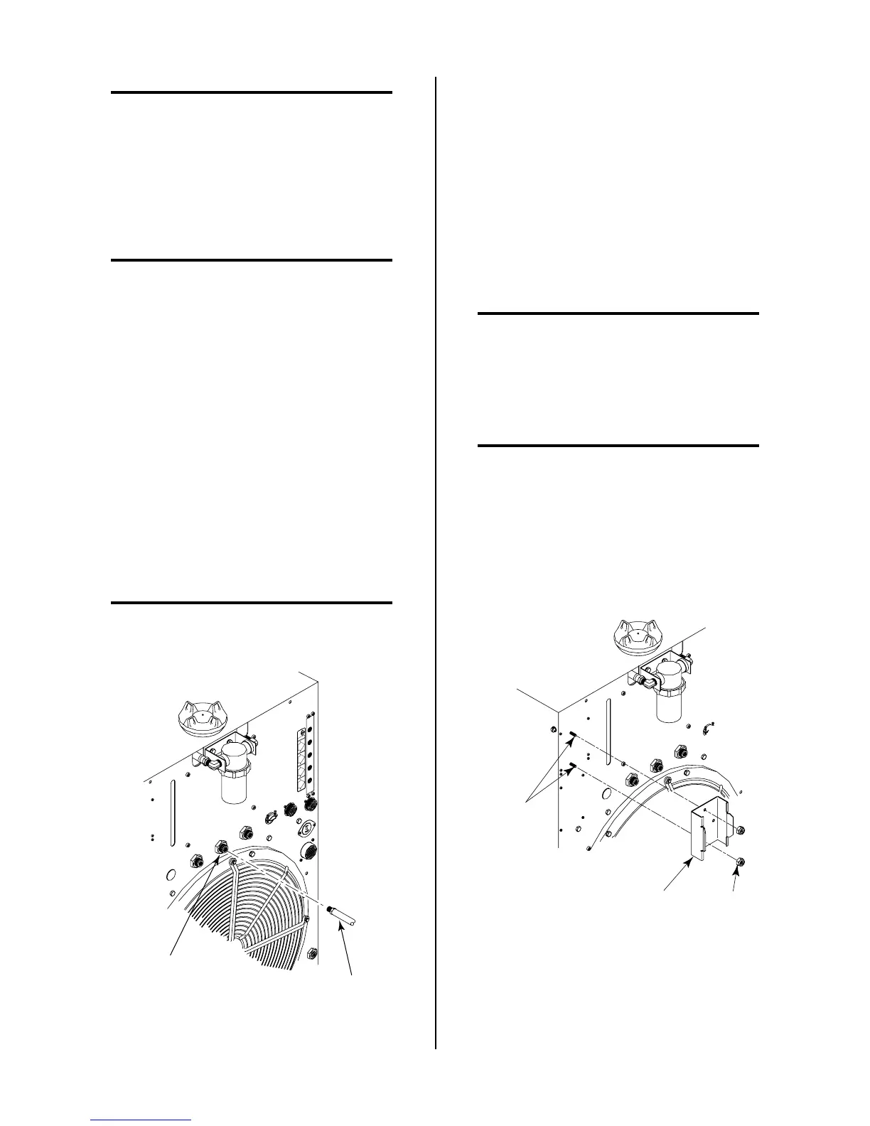
2. Locate the two mounting studs on the rear of the unit
and secure the Air Filter Mounting Bracket to the panel
using the two 10-32 Nylon Locking Nuts provided.
Air Filter
Mounting Bracket
Mounting
Nuts
Mounting
Studs
A-01336
Figure 3-12 Air Filter Mounting Bracket Installation
3. Place thread sealer on the threads of the 1/4 NPT Street
Elbow (see NOTE).