Manual 0-2568 21 INSTALLATION PROCEDURES
NOTE
Do Not use teflon tape as a thread sealer as small
particles of the tape may break off and cause the
small gas passage to be blocked in the torch.
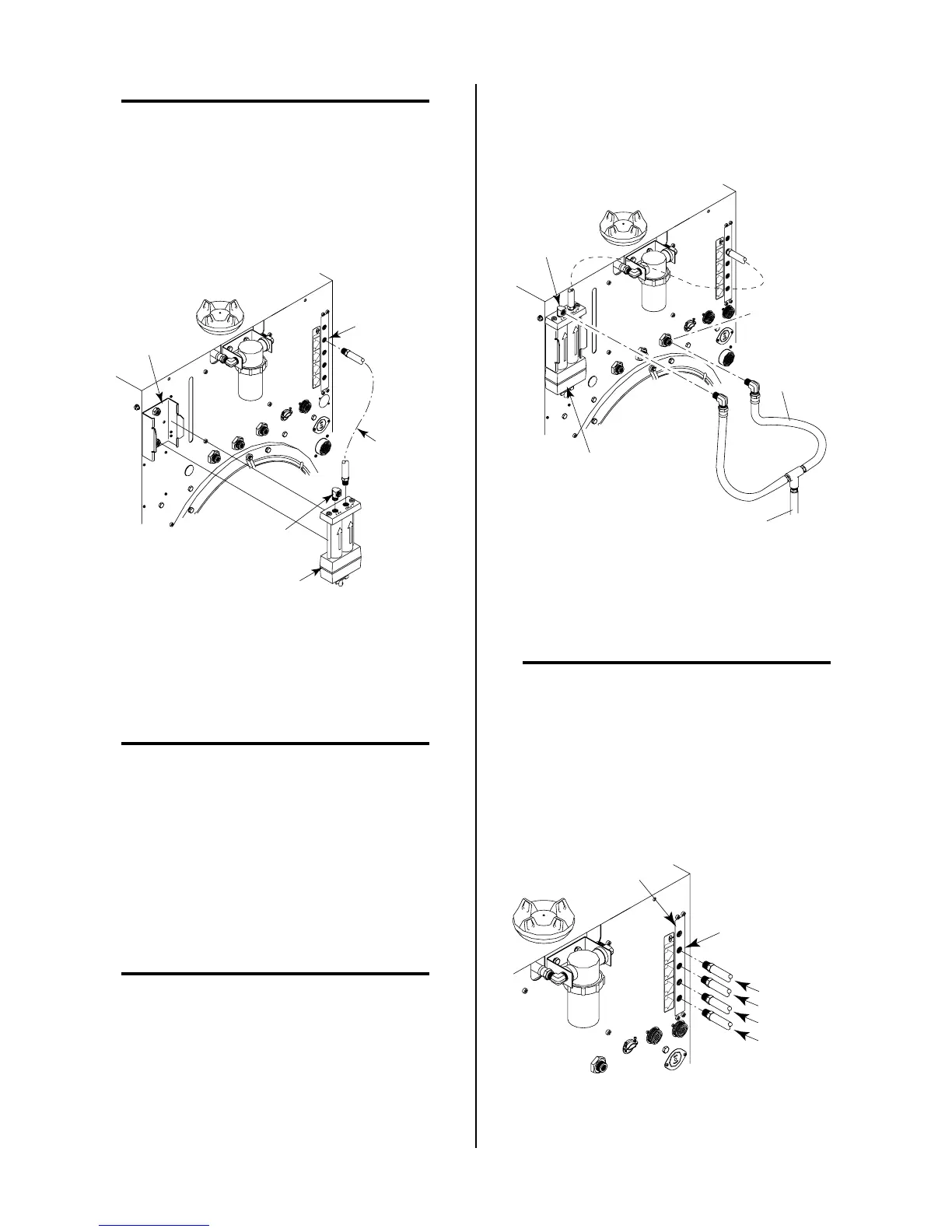
4. Install the supplied 1/4 NPT Street Elbow into the
input port (IN) of the Air Line Filter Assembly.
5. Slide the Air Line Filter Assembly into the mounting
bracket. The Filter Assembly will snap into place.
A-01339
1/4 NPT
Elbow
Air Filter
Assembly
Air Filter
Mounting
Bracket
OUTPUTOUTPUT
TO
CONTROLCONTROL
MODULEMODULE
AIRAIR
PLASMAPLASMA
INPUTINPUT
N
2
PLASMAPLASMA
INPUTINPUT
O
2
PLASMAPLASMA
INPUTINPUT
PLASMA GASPLASMA GAS
Ar/HAr/H
2
PLASMAPLASMA
INPUTINPUT
Hose
Assembly
Filter to
Plasma
Gas Input
Gas Control
Plasma Gas
Input Fitting
Figure 3-13 Supply Hose Connections With Gas
Control Option
6. Place thread sealer on the threads of the connectors at
both ends of the Filter to Plasma Input Gas Hose As-
sembly (see NOTE).
NOTE
Do Not use teflon tape as a thread sealer as small
particles of the tape may break off and cause the
small gas passage to be blocked in the torch.
7. Connect the Filter to Plasma Input Gas Hose Assem-
bly to the output port (OUT) of the Air Line Filter
Assembly and to the Air Plasma Input Fitting on the
Gas Control Manifold.
8. Place thread sealer on the threads of the Street Elbow
on a Y-Hose Assembly (see NOTES).
NOTES
Do Not use teflon tape as a thread sealer as small
particles of the tape may break off and cause the
small gas passage to be blocked in the torch.
The Y-Hose Assembly is customer supplied and is
shown to illustrate one method of connecting the
customer's air supply.
9. Connect the air supply hose from a Y-Hose Assembly
to the street elbow on the Air Line Filter input port
(IN). The Y-Hose Assembly should have already been
installed, if shop air was being used as the plasma
and secondary gases.
A-01340
Air Filter
Assembly
Shop Air
Gas Input
OUTPUTOUTPUT
TO
CONTROLCONTROL
MODULEMODULE
AIRAIR
PLASMAPLASMA
INPUTINPUT
N
2
PLASMAPLASMA
INPUTINPUT
O
2
PLASMAPLASMA
INPUTINPUT
PLASMA GASPLASMA GAS
Ar/HAr/H
2
PLASMAPLASMA
INPUTINPUT
Secondary Air
Gas Fitting
Y-Hose
Assembly
From Supply
Figure 3-14 Supply Hose Connections Wit Gas
Control Option
10. Apply thread sealer (see NOTE) to the other elbow of
the Y-Hose Assembly.
NOTE
Do Not use teflon tape as a thread sealer as small
particles of the tape may break off and cause the
small gas passage to be blocked in the torch.
11. Connect the elbow fitting to the SECONDARY (Air)
1/4 NPT fitting.
12. Connect the other required plasma gases to the op-
tional Gas Control gas manifold.
A-01341
OUTPUT
TO
CONTROLCONTROL
MODULEMODULE
AIRAIR
PLASMAPLASMA
INPUTINPUT
N
2
PLASMAPLASMA
INPUTINPUT
O
2
PLASMAPLASMA
INPUTINPUT
PLASMA GASPLASMA GAS
Ar/HAr/H
2
PLASMAPLASMA
INPUTINPUT
N2
Gas Control Plasma
Gas Manifold
Air (Filtered)
O
2
Ar/H2
Plasma Gas
Input Fittings
Figure 3-15 Plasma Gas Connections