16
UNIT OPERATING INSTRUCTIONS STANDARD TSR/TSR-3 HMI CONTROLLER
DISPLAY
The display presents information to the
operator. This information includes setpoint
and box temperature, hourmeter readings,
alarms and several icons as shown below. All
display segments and icons are shown below
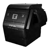
Display
The upper row of numbers can display the Box
Temperature, Engine Run Time Hourmeter or
Alarm Code(s).
The lower row of numbers can display the
Setpoint, Electric Run Time Hourmeter or Total
Number of Alarms.
The meaning of the display icons are shown in
the table below.
KEYS AND LED INDICATORS
There are nine touch sensitive keys. Some of
these keys have more than one function as
shown below.
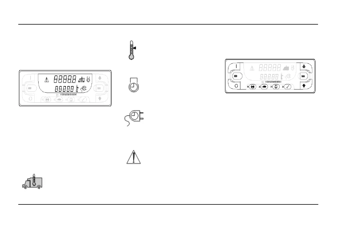
Keys and LED Indicators
There are amber indicator LED's located next
to each of the four function keys below the
display. The LED will glow amber when that
function is active.
A red indicator LED is located between the ON
Key and OFF Key at the left side of the display.
This indicator will glow if Alarm Code 91
Check Electric Ready Input occurs. It will also
light if a 15 pin Thermo King data cable is
connected to the serial port on the back of the
controller (DPD).
The primary and secondary key uses are shown
in the table below. If the key has more than one
use the primary use is shown first.
When this icon is present the
upper display is showing the
actual box temperature inside the
truck box.
When this icon is present the
lower display is showing the
current setpoint.
When this icon is present the
upper display is showing the
diesel engine run time.
When this icon is present the
lower display is showing the
electric motor run time (if the unit
equipped with optional
ELECTRIC STANDBY).
When this Alarm Icon is present
one or more alarm conditions
have occurred. If the display is
not flashing any alarms are
Check Alarms. If the display is
flashing on and off a shutdown
alarm has occurred and the unit
has been shut down. Immediate
action must be taken.
 Loading...