© 2016 Thorlabs Scientific Imaging460
DCx Camera Functional Description and SDK Manual
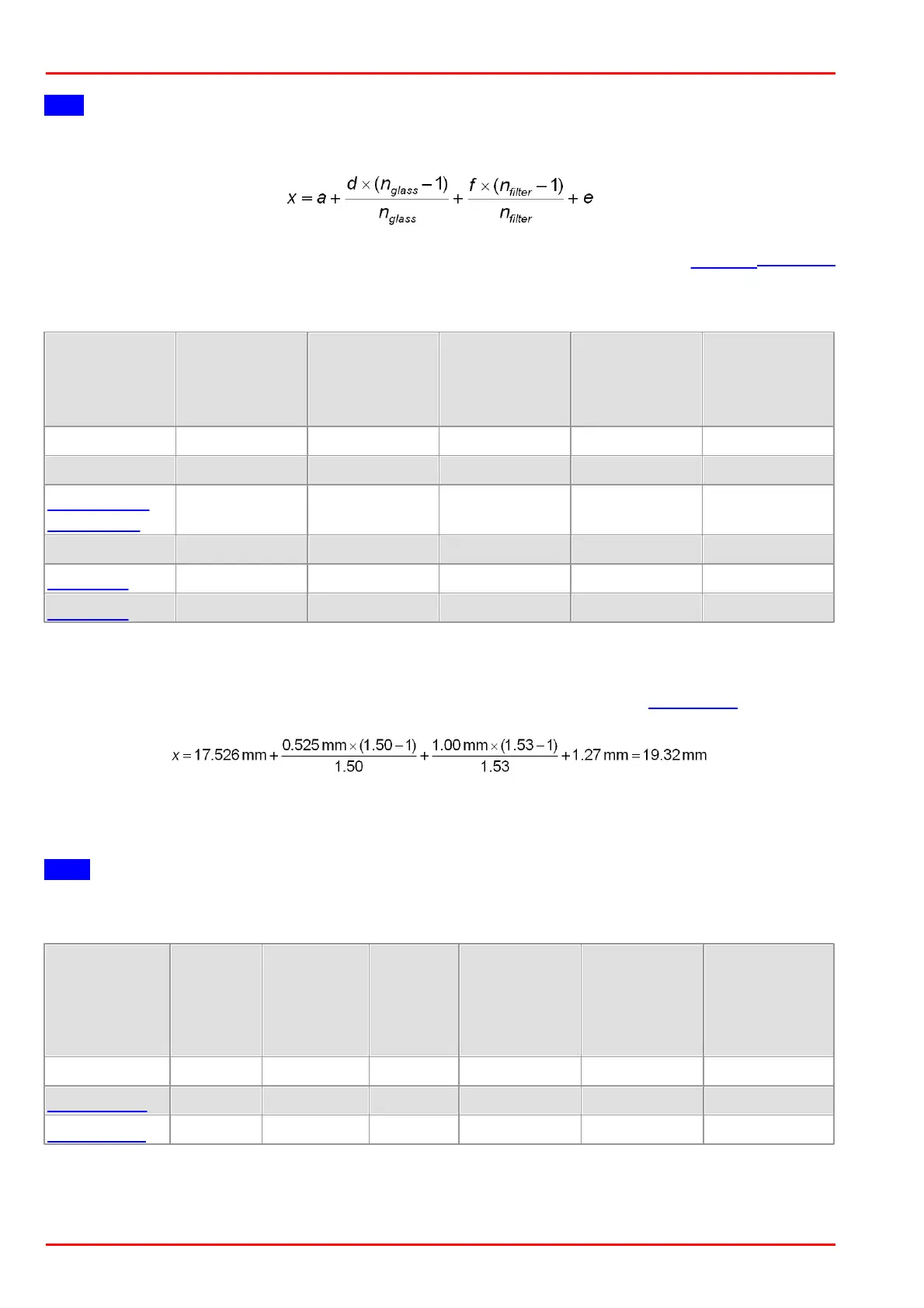
Hint
You can use the following formula to calculate the mechanical flange back distance:
The tolerances for the position accuracy of DCx camera sensors are given in the Position accuracy
chapter.
Calculating the flange back distance for DCx Cameras with C-mount
Thickness
sensor glass
[mm]
Active sensor
area to PCB
[mm]
Flange to
active sensor
area without
filter glass[mm]
Flange to
active sensor
area with filter
glass [mm]
Sensor height
above the
PCB
[mm]
Calculation example: UI-154x-xx with IR-cut filter
(a = 17.526 mm, d = 0.525 mm, nGlass = 1.50, f = 1mm, nFilter = 1.53; see Filter types table)
Calculating the flange back distance for DCC1545M and DCC1645C cameras with CS-
mount
Note
For these cameras with CS-mount, the flange back distance is only 12.526 mm.
Thickness
sensor
glass
[mm]
Active
sensor area
to PCB
[mm]
Threaded
flange to
active
sensor
area
Flange to
active sensor
area without
filter
glass[mm]
Flange to
active sensor
area with filter
glass [mm]
Sensor height
above the PCB
[mm]
 Loading...