© 2016 Thorlabs Scientific Imaging
5 Specifications
481
5.5.2.5 RS-232 Serial Interface
Attention
The General Purpose IO are not potential-free and have no protective circuit. Faulty wiring
(overvoltage, undervoltage or inverting the wiring when used as serial interface) can result in a
damage in the electronics.
During operation as serial interface only LVCMOS levels are allowed to the connector pins. To get
a serial RS-232 compliant interface, an external level shifter (LVCMOS/RS-232) is required.
Applying RS-323 levels directly to the pins as well as mixing up the signals RxD and TxD can
destroy the camera electronics!
Serial interface specification
9.600
19.200
38.400
57.600
115.200
Note
With the 8N1 mode, the maximum payload data rate achievable is 80% of the selected baud rate.
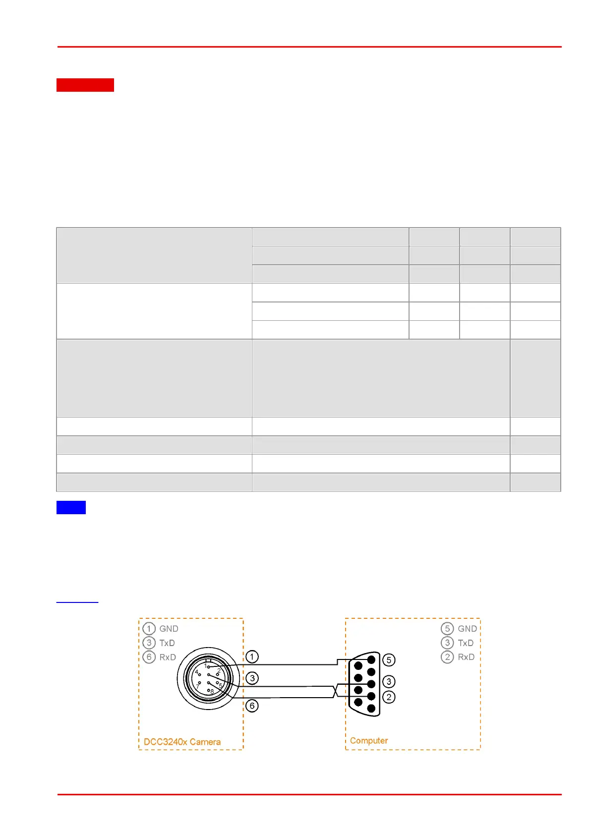
Serial interface wiring (UART)
The following figure shows the wiring of the serial interface with GPIO 1 as camera-side output
(TxD) and GPIO 2 as camera-side input (RxD). The GPIO must be configured accordingly (see
is_IO()).
Serial interface connector (UART)
 Loading...