© 2016 Thorlabs Scientific Imaging
5 Specifications
473
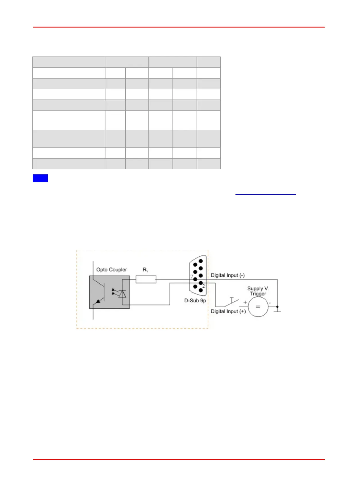
5.5.1.2 Digital Input (Trigger) Circuit
Digital input specifications
Trigger pulse width
(edge)
Note
*
)
For information on how to determine the USB board revision, please refer to the DCx Driver Compatibility chapter.
For interpreting the trigger signal, either the negative or the falling edge can be used. The digital input is
galvanically isolated using an opto coupler to protect the camera and the PC against surges. Only
DC voltages may be applied to the digital input.
Digital input wiring
Wiring of the trigger connector
 Loading...