FUNCTION CHARACTERISTICS
101
NVA100X-D - Manual - 02 - 2016
Likewise, the start of the second threshold is issued when both the conditions concerning the alarm
element are fi lled and the R
L1
and X
L1
computed values are placed inside the circle with equation:
R
L1
2
+(X
L1
+ X
C2
)
2
≤ (X
D2
/2)
2
2)
where the absolute coordinate of the center is X
C2
and the diameter X
D2
are adjustable.
After expiry of the associated operate time (t
XC2XD2
) a trip command is issued.
[1]
Setting for MOTOR mode
Reference: connection diagram shown in fi g. 3
The start of the alarm element is issued when both the following conditions are fi lled:
X
L1
≤ -KR
L1
R
L1
≤ 0
or when both the following conditions are fi lled:
X
L1
≤ KR
L1
R
L1
> 0
where K is the adjustable angular coeffi cient (10° ≤ α ≤ 75°, K = tanα).
After expiry of the associated operate time (t
40AL
) a trip command is issued.
The start of the fi rst element is issued when both the conditions concerning the alarm element are
fi lled and the R
L1
and X
L1
computed values are placed inside the circle with equation:
R
L1
2
+(X
L1
- X
C1
)
2
≤ (X
D1
/2)
2
3)
where the absolute coordinate of the center is X
C1
and the diameter X
D1
are adjustable.
After expiry of the associated operate time (t
XC1XD1
) a trip command is issued.
Likewise, the start of the second threshold s issued when both the conditions concerning the alarm
element are fi lled and the R
L1
and X
L1
computed values are placed inside the circle with equation:
R
L1
2
+(X
L1
- X
C2
)
2
≤ (X
D2
/2)
2
4)
where the absolute coordinate of the center is X
C2
and the diameter X
D2
are adjustable.
After expiry of the associated operate time (t
XC2XD2
) a trip command is issued
[2]
Operating logic
For both operating modes (Motor or Generator):
A undervoltage consensus may be selected for all three thresholds, having the adjustable thresh-
old U
SUP
<: the consensus has the purpose of avoiding any undesired alarms or tripping of the de-
vice when the machine is operating as a synchronous compensator. The Undervoltage consensus
enables the three protective device thresholds when all three voltages together drop below the
threshold U
SUP
<, otherwise the three thresholds are inhibited.
Note 1 Since the center coordinates XC1 and XC2 are adjustable inside positive range, the center of circle with equations 1) and 2) are always located
along the negative axis XL1
Note 1 Since the center coordinates XC1 and XC2 are adjustable inside positive range, the center of circle with equations 3) and 4) are always located
along the negative axis XL1
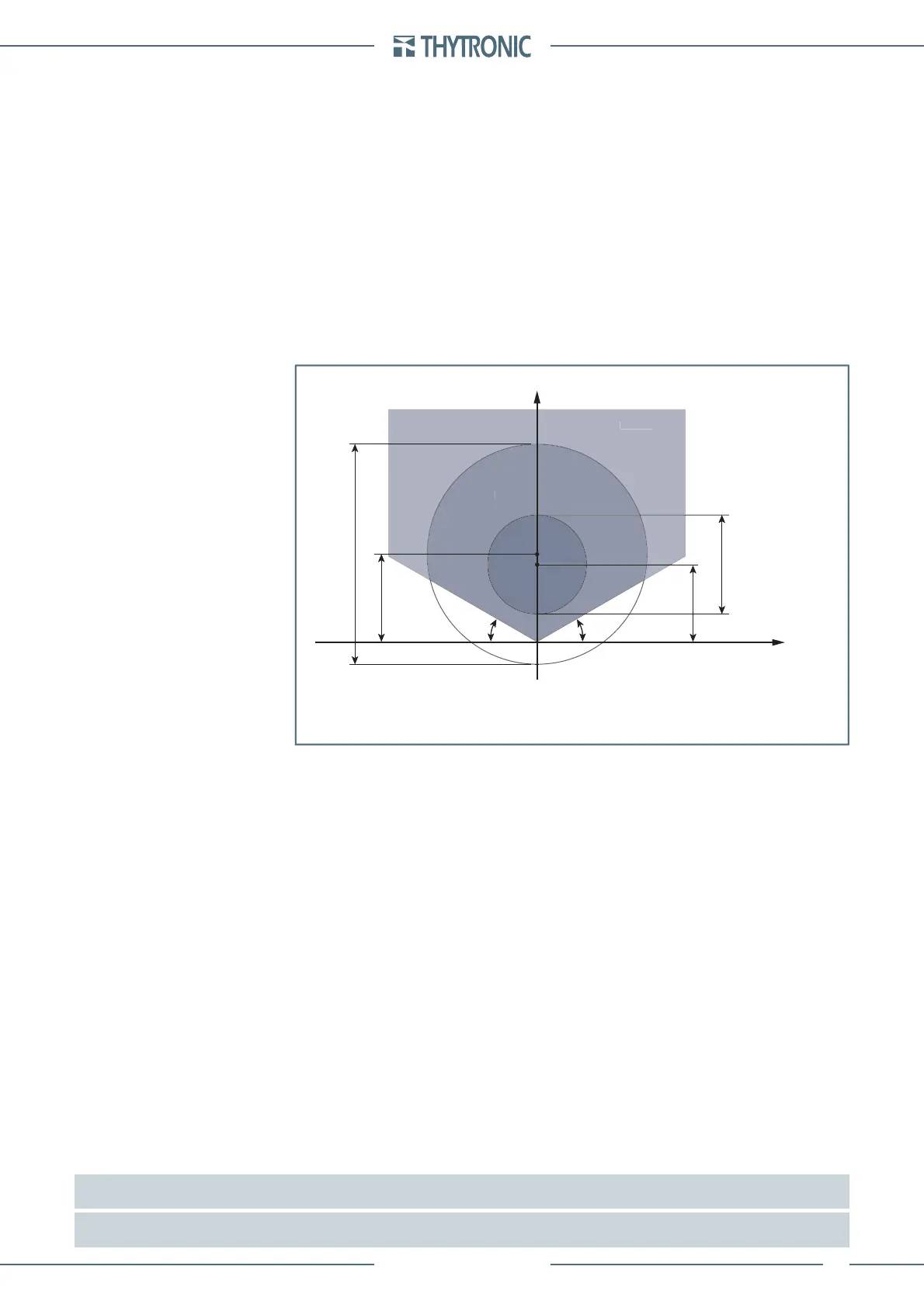
•
X
L1
(p.u. Z
nf
)
αα
R
L1
(p.u. Z
nf
)
TRIP
TRIP
ALARM
X
D2
X
C1
X
D1
NO TRIP NO TRIP
NO TRIP
X
C2
General operation R-X characteristic for the loss of field element - 40 in the RL1-XL1 plane with
Mode40 = MOTOR setting
LARM
X
L1
(p.u. Z
nf
)
αα
R
L1
(p.u. Z
nf
)
TRIP
TRIP
ALARM
X
D2
X
C1
X
D1
NO TRIP NO TRIP
NO TRIP
X
C2
General operation R-X characteristic for the loss of field element - 40 in the RL1-XL1 plane with
Mode40 = MOTOR setting
 Loading...


