102
NVA100X-D - Manual - 02 - 2016
FUNCTION CHARACTERISTICS
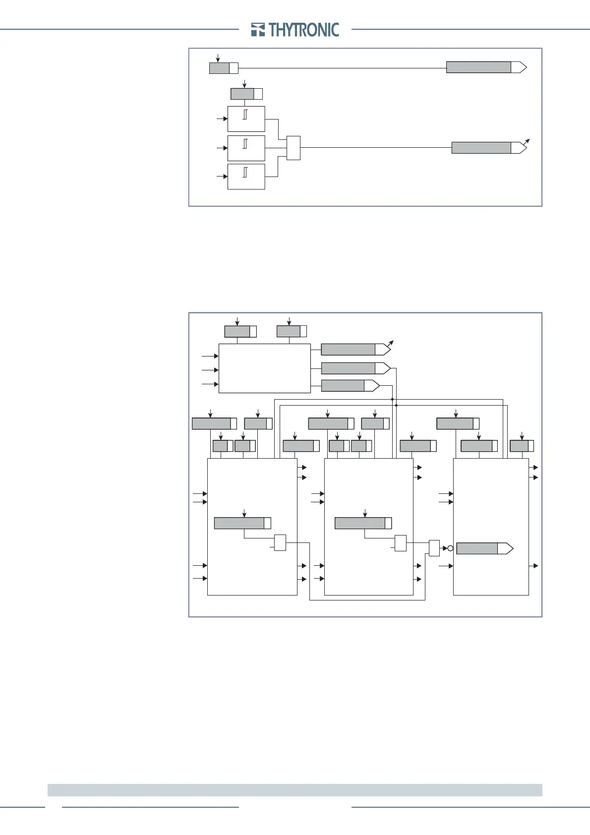
In order to set the undervoltage consent, the minimum voltage threshold may be set (STATE ON)
for the USUPU< inside the Set \ Profi le A (or B) \ Loss of fi eld-40 \ Common confi guration menu.
Every threshold may be enabled or disabled by setting ON or OFF the 40AL Enable, XC1XD1
Enable, XC2XD2 Enable parameters inside the Set \ Profi le A (or B) \ Loss of fi eld-40 \ 40AL Ele-
ment, XC1-XD1 Element , XC2-XD2 Element menus.
The trip of the 40AL element may be inhibited by the start of the fi rst and/or the second element
by setting ON the Disabling 40AL by XC1-XD1 start, Disabling 40AL by XC2-XD2 start,
parameters available inside the Set \ Profi le A(or B) \ Loss of fi eld-40 \ XC1-XD1 Element ( XC2-XD2
Element) menus.
The protection elements are blocked off whenever the VT supervision function are active, so that
no unwanted trip can arise if any fault on the VTs secondary circuits (break, fuse trip, etc) are
detect;
[1]
the Block functions enable from 74VT parameter (74VT-BK-EN) is available inside the
Set \ VT supervision - 74VT menus.
Note 1 The exhaustive treatment of the VT and CT supervision function may be found inside the CONTROL AND MONITORING section.
•
•
•
all-F40.ai
U
23
U
12
U
31
Z
L1
Z
L1
Z
L1
Block1
Block1
Block3
Block1
Block3
BF
Block1
BF
Block1
Block1
Alpha40AL
t
40AL
X
C2
X
D2
Element
X
C1
X
D1
Element
Alarm Element
X
C2
X
D2
Start
X
C2
X
D2
Start
X
C2
X
D2
Trip
X
C1
X
D1
Start
X
C1
X
D1
Start
X
C1
X
D1
Trip
Alpha Start
Alpha Trip
X
C2
X
D2
&
≥
40ALdisbyXC1XD1 40ALdisbyXC2XD2
&
Mode
Common configuration
U
SUP
<
Operating Mode
Start undervoltage
Start undervoltage Start undervoltage
Alarm inhibition
X
C2
X
D2
Enable
X
C1
X
D1
t
XC1XD1
t
XC2XD2
t
XC1XD1-RES
t
XC2XD2-RES
X
C1
X
D1
Enable 40 AL Enable
Start undervoltage
Undervoltage enable
Logic diagram concerning the loss of field element - 40
Undervoltage F40.ai
Start undervoltage
Undervoltage enable
(ON≡Enable)
State
U
12
≤U
SUP
<
U
SUP
<
&
U
12
U
23
≤U
SUP
<
U
23
U
31
≤U
SUP
<
U
31
Logic diagram concerning the undervoltage consent for the loss of field element - 40
 Loading...


