FUNCTION CHARACTERISTICS
245
NVA100X-D - Manual - 02 - 2016
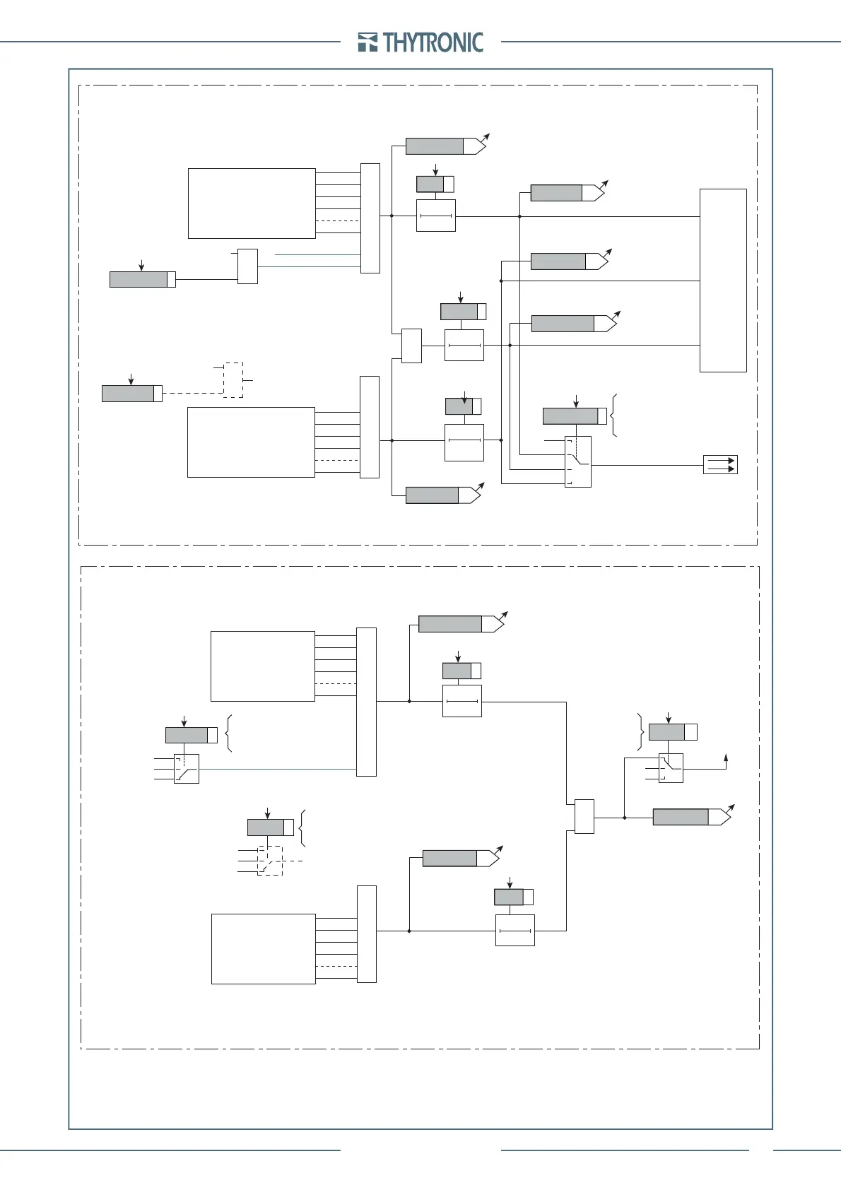
Block2out diagram
Pilot wire output
BLOUT1
TRIPPING MATRIX (LED+RELAYS)
ModeBLOUT1
A
B
C
D
≥1
t
F-IPh
t
F-IPh/IE
t
F-IE
ST-Iph BLK2
ST-IE BLK2
≥1
T0
t
F-IPh/IE
T0
t
F-IPh
T0
t
F-IE
BLK2OUT-Iph
BLK2OUT-Iph/IE
BLK2OUT-IE
&
xxBLK2OUT
Start xx
A = OFF
B = ON IPh
C = ON IPh/IE
D = ON IE
BLK2OUT-IPh-K
BLK2OUT-IPh-L
BLK2OUT-IPh/IE-K
BLK2OUT-IPh/IE-L
BLK2OUT-IE-K
BLK2OUT-IE-L
87T Block2 OUT
Start 87T
&
Block2 output
(ON≡Enable)
87TBLK2OUT
Block4-in-out-diagram
Logic diagram of the logic blocking signals
(Block4)
t
FI-Iph
ST-IE BLK4
ST-Iph BLK4
≥1
≥1
t
FI-IE
Block4 OUT
≥1
T0
t
FI-Iph
T0
t
FI-IE
xx Block4 OUT
Block4
A = IN
B = OFF
C = OUT
B
C
“0”
“0”
A = IN
B = OFF
C = OUT
87TBLK4
Start 87T
C
B
A
“0”
“0”
Block4 enable
A = IN
B = OFF
C = OUT
xxBLK4
Start xx
C
B
A
“0”
“0”
xxBLK4
A
87T Block4
All other BLK2OUT outputs
of ground elements
(see BLK2OUT chapter)
≥1
All BLK2OUT outputs
of phase elements
(see BLK2OUT chapter)
All BLK4 I/O
of phase elements
(see BLK4chapter)
All BLK4 I/O
of ground elements
(see BLK4chapter)
Differential protection (
87G-87M-87T
) - Logic diagram of the blocking signals
 Loading...


