254
NVA100X-D - Manual - 02 - 2016
FUNCTION CHARACTERISTICS
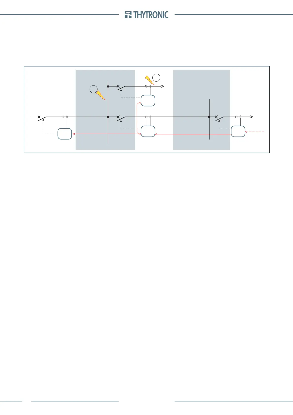
In the following example the output pulses must be enabled inside the device B only (2nd logic se-
lectivity level) and D (1st logic selectivity level).
Setting example
In reference to the above shown schematic diagram, the logic selectivity is performed by means of
the dedicated I/O for the short circuit elements of A, B and C protective relays, so that if a fault arises
in (2), the open order or circuit breaker CB2 is issued and no trip is issued by A device.
A command must be issued for the main circuit breaker CB1 by the A relay with a fault in (1).
A Protection
I>> element with defi nite time set to 4.5 I
n
with operate time to 0.10 s blocked by start of B and/or C
protection.
Settings:
I>>
def
= 4.5 I
n
t>>
def
= 0.100 s
PulseBLOUT1 = OFF
PulseBLIN1 = 1 s
I>>BLK2IN = ON
I>>BLK2OUT = OFF
t
B-IPh
= 0.30 s
B Protection
I>> element with defi nite time set to 4.0 I
n
with operate time to 0.10 s with emission of block output
toward A protection relay.
Settings:
I>>
def
= 4.0 I
n
t>>
def
= 0.100 s
I>>BLK2IN = OFF
I>>BLK2OUT = ON
PulseBLIN1 = OFF
PulseBLOUT1 = 1 s
t
F-IPh
= 0.25 s
C Protection
I>> element with defi nite time set to 4.0 I
n
with operate time to 0.10 s with emission of block output
toward A device and block input from D protection relay.
Settings:
I>>
def
= 4.0 I
n
t>>
def
= 0.100 s
I>>BLK2IN = ON
I>>BLK2OUT = ON
PulseBLIN1 = 1 s
PulseBLOUT1 = OFF
t
F-IPh
= 0.25 s
t
B-IPh
= 0.30 s
•
•
•
•
•
•
•
•
•
•
•
•
•
•
•
•
•
•
•
•
•
•
LOAD
Pro_N
Pro_N
Pro_N
Pro_N
logica_acc-esempio.ai
BLIN1
BLOUT1 BLOUT1
BLOUT1
BLIN1
BLIN1
TRIP
TRIP
TRIP
2° level of logic selectivity 1° level of logic selectivity
TRIP
1
2
B
CD
A
Logic selectivity
 Loading...


