INSTALLATION
297
NVA100X-D - Manual - 02 - 2016
Any change of the Ethernet communication parameters become active only after an hw reset
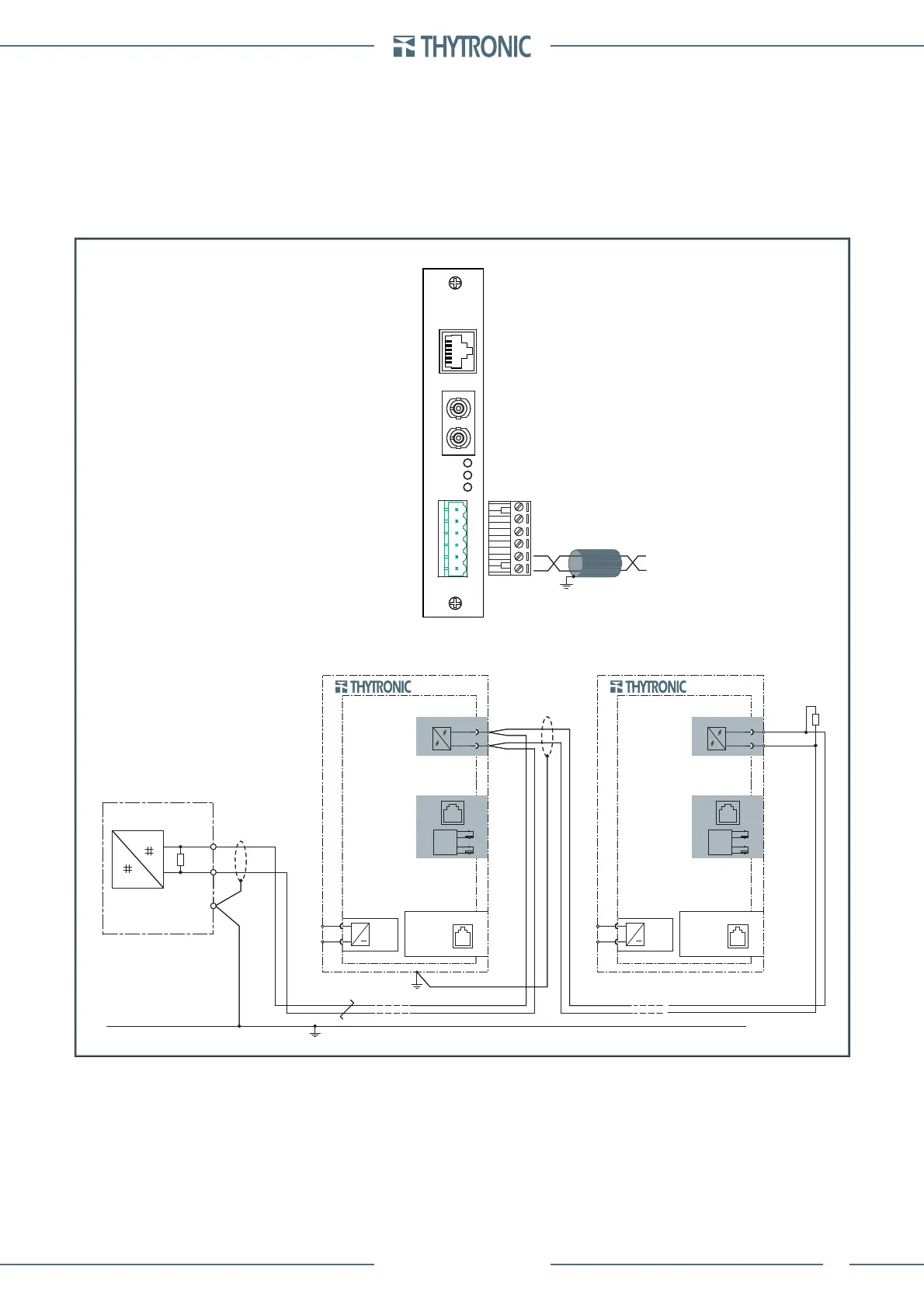
RS485 port
RS485 communication circuit connections must be made using screened twisted pair cable observ-
ing the polarities; screening must only be connected to the end terminating at the RS485 interface
circuit pertaining to the monitoring unit.
It is recommended to terminate the line at the extremities of the same; this must be performed on the
RS485 line control unit and on the NA80 device placed at the furthest point connecting the specially
provided resistor; termination can be made by means a jumper between the F2-F3 terminals.
Termination resistors allow adjusting the impedance of the line, reducing the infl uence of the induc-
tive components of the same, which might compromise good communication.
RS485
120 Ω
120 Ω
SUPERVISION UNIT
A+
B-
RS485-wiring.ai
X5
X6
NVA100X
U
AUX
≅
ETH-1
ETH-2
ETHERNET
1 - DTR
2 - GND
3 - RX
4 - TX
RS232
RS485
A+
B-
X5
X6
NVA100X
U
AUX
≅
ETH-1
ETH-2
ETHERNET
1 - DTR
2 - GND
3 - RX
4 - TX
RS232
RS485
A+
B-
4
6
5
2
1
3
x
NETWORK
3V3
FX
TX
LINK2
LINK1
RS485
B-
A+
RS485
120 Ω
120 Ω
SUPERVISION UNIT
A+
B-
RS485-wiring.ai
X5
X6
NVA100X
U
AUX
≅
ETH-1
ETH-2
ETHERNET
1 - DTR
2 - GND
3 - RX
4 - TX
RS232
RS485
A+
B-
X5
X6
NVA100X
U
AUX
≅
ETH-1
ETH-2
ETHERNET
1 - DTR
2 - GND
3 - RX
4 - TX
RS232
RS485
A+
B-
4
6
5
2
1
3
x
NETWORK
3V3
FX
TX
LINK2
LINK1
RS485
B-
A+
 Loading...


