48
NVA100X-D - Manual - 02 - 2016
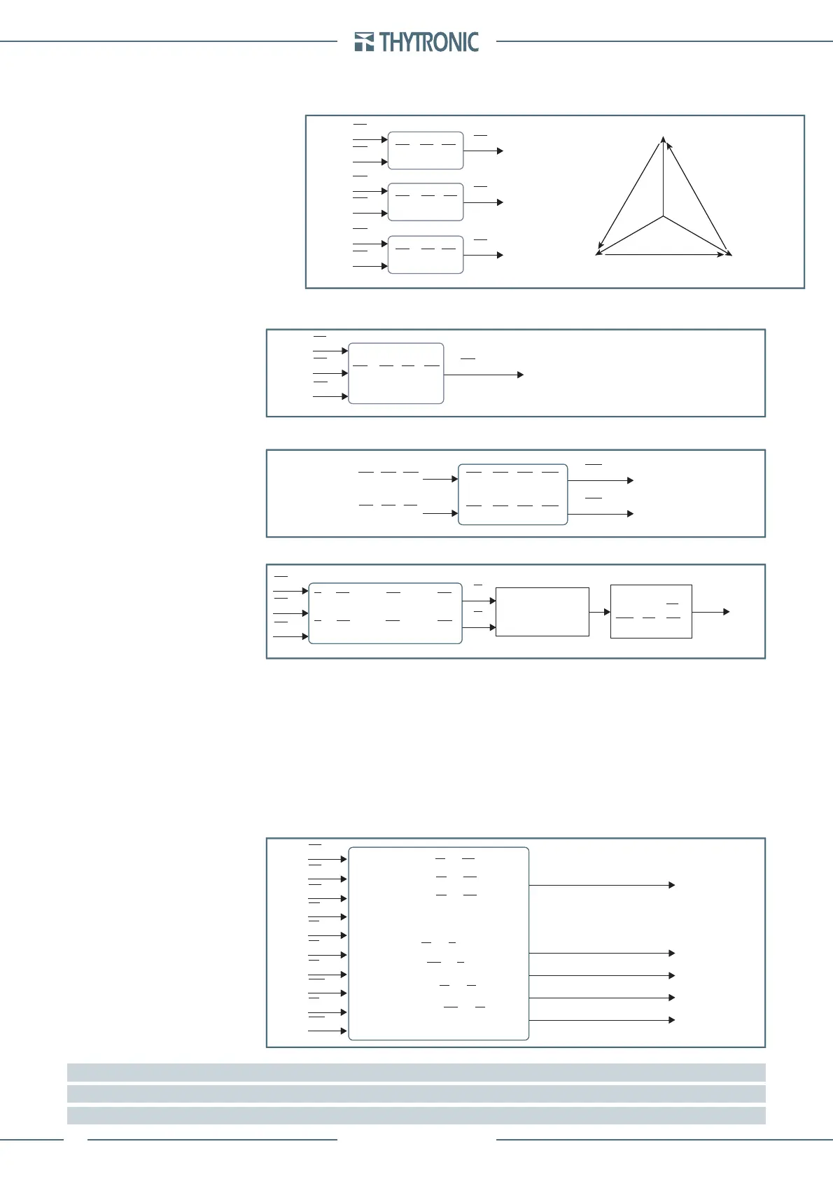
FUNCTION CHARACTERISTICS
By means vector addition of direct measures the following are calculated (RMS value of fundamen-
tal components):
Phase-to-phase voltages: U
12
, U
23
, U
31
Fundamental component of the calculated residual voltage U
EC
[1]
Fundamental component of the calculated residual currents I
ECH
and I
ECL
[2]
Thermal image Δθ
Phase
[3]
Displacement angle of any phase current respect the corresponding phase-to-neutral voltage:
Phi
L1
, Phi
L2
, Phi
L3
,
Displacement angle of the measured residual current respect the measured residual voltage (posi-
tive with current in lagging direction in respect to voltage): Phi
E
,
Displacement angle of the measured residual current respect the calculated residual voltage (pos-
itive with current in lagging direction in respect to voltage): Phi
EC
Displacement angle of the calculated residual current respect the measured residual voltage (pos-
itive with current in lagging direction in respect to voltage): Phi
E_IEC
Displacement angle of the calculated residual current respect the calculated residual voltage
(positive with current in lagging direction in respect to voltage): Phi
EC_IEC
Note 1 The residual voltage is available as a direct measure U
E
and computed measure U
EC
,
Note 2 The residual currents are available with either direct measurement (IE1 and IE2) and as calculated measure (I
ECH
and I
ECL
)
Note 3 The adjustment and display range of displacements are 0°... 359°
•
•
•
•
•
•
•
•
•
U12.ai
U
L1
U
12
=
U
L1
-
U
L2
U
12
U
23
U
31
U
23
=
U
L2
-
U
L3
U
31
=
U
L3
-
U
L1
U
L2
U
L2
U
L3
U
L1
U
L3
(U
n
)
(U
n
)
(U
n
)
U
L1
U
12
U
31
U
23
U
L3
U
L2
U12.ai
U
L1
U
12
=
U
L1
-
U
L2
U
12
U
23
U
31
U
23
=
U
L2
-
U
L3
U
31
=
U
L3
-
U
L1
U
L2
U
L2
U
L3
U
L1
U
L3
(U
n
)
(U
n
)
(U
n
)
U
L1
U
12
U
31
U
23
U
L3
U
L2
UEC.ai
U
L1
U
EC
=
U
L1
+
U
L2
+
U
L3
U
EC
U
L3
U
L2
(U
En
)
UEC.ai
U
L1
U
EC
=
U
L1
+
U
L2
+
U
L3
U
EC
U
L3
U
L2
(U
En
)
IEC.ai
I
ECH
=
I
L1H
+
I
L2H
+
I
L3H
I
ECH
I
ECH
=
I
L1H
+
I
L2H
+
I
L3H
(I
nH
)
I
ECL
(I
nL
)
I
L1H
, I
L2H
, I
L3H
I
L1L
, I
L2L
, I
L3L
IEC.ai
I
ECH
=
I
L1H
+
I
L2H
+
I
L3H
I
ECH
I
ECH
=
I
L1H
+
I
L2H
+
I
L3H
(I
nH
)
I
ECL
(I
nL
)
I
L1H
, I
L2H
, I
L3H
I
L1L
, I
L2L
, I
L3L
Theta.ai
I
L1L
I
2
I
2
= (I
L1L
+ e
-j120°
I
L2L
+ e
+j120°
I
L3L
)
I
1
= (I
L1L
+ e
+j120°
I
L2L
+ e
-j120°
I
L3L
)
I
L3L
I
L2L
I
1
I
th
= √(I
1
2
+ K
2
2
∙I
2
2
)
Δθ
(Δθ
B
)
2
dΔθ
dt
I
B
I
th
Δθ
T+ T+
( )
+=
Theta.ai
I
L1L
I
2
I
2
= (I
L1L
+ e
-j120°
I
L2L
+ e
+j120°
I
L3L
)
I
1
= (I
L1L
+ e
+j120°
I
L2L
+ e
-j120°
I
L3L
)
I
L3L
I
L2L
I
1
I
th
= √(I
1
2
+ K
2
2
∙I
2
2
)
Δθ
(Δθ
B
)
2
dΔθ
dt
I
B
I
th
Δθ
T+ T+
( )
+=
Fase.ai
ϕ
L1
= I
L1
- U
L1
Phi
L1
, Phi
L2
,Phi
L3
Phi
E
Phi
EC
(° )
(° )
(° )
U
L1
ϕ
L2
= I
L2
- U
L2
ϕ
L3
= I
L3
- U
L3
ϕ
E
= U
E
- I
E
ϕ
EC
= U
EC
- I
E
Phi
E_IEC
Phi
EC_IEC
(° )
(° )
ϕ
E_IEC
= U
E
- I
EC
ϕ
EC_IEC
= U
EC
- I
EC
U
L2
U
L2
I
L1L
I
L2L
I
L3L
U
E
U
EC
I
EC
I
E
Fase.ai
ϕ
L1
= I
L1
- U
L1
Phi
L1
, Phi
L2
,Phi
L3
Phi
E
Phi
EC
(° )
(° )
(° )
U
L1
ϕ
L2
= I
L2
- U
L2
ϕ
L3
= I
L3
- U
L3
ϕ
E
= U
E
- I
E
ϕ
EC
= U
EC
- I
E
Phi
E_IEC
Phi
EC_IEC
(° )
(° )
ϕ
E_IEC
= U
E
- I
EC
ϕ
EC_IEC
= U
EC
- I
EC
U
L2
U
L2
I
L1L
I
L2L
I
L3L
U
E
U
EC
I
EC
I
E
 Loading...


