Feedback Controlyzer DigiLock 110
Page 64
Status: 5.12.17
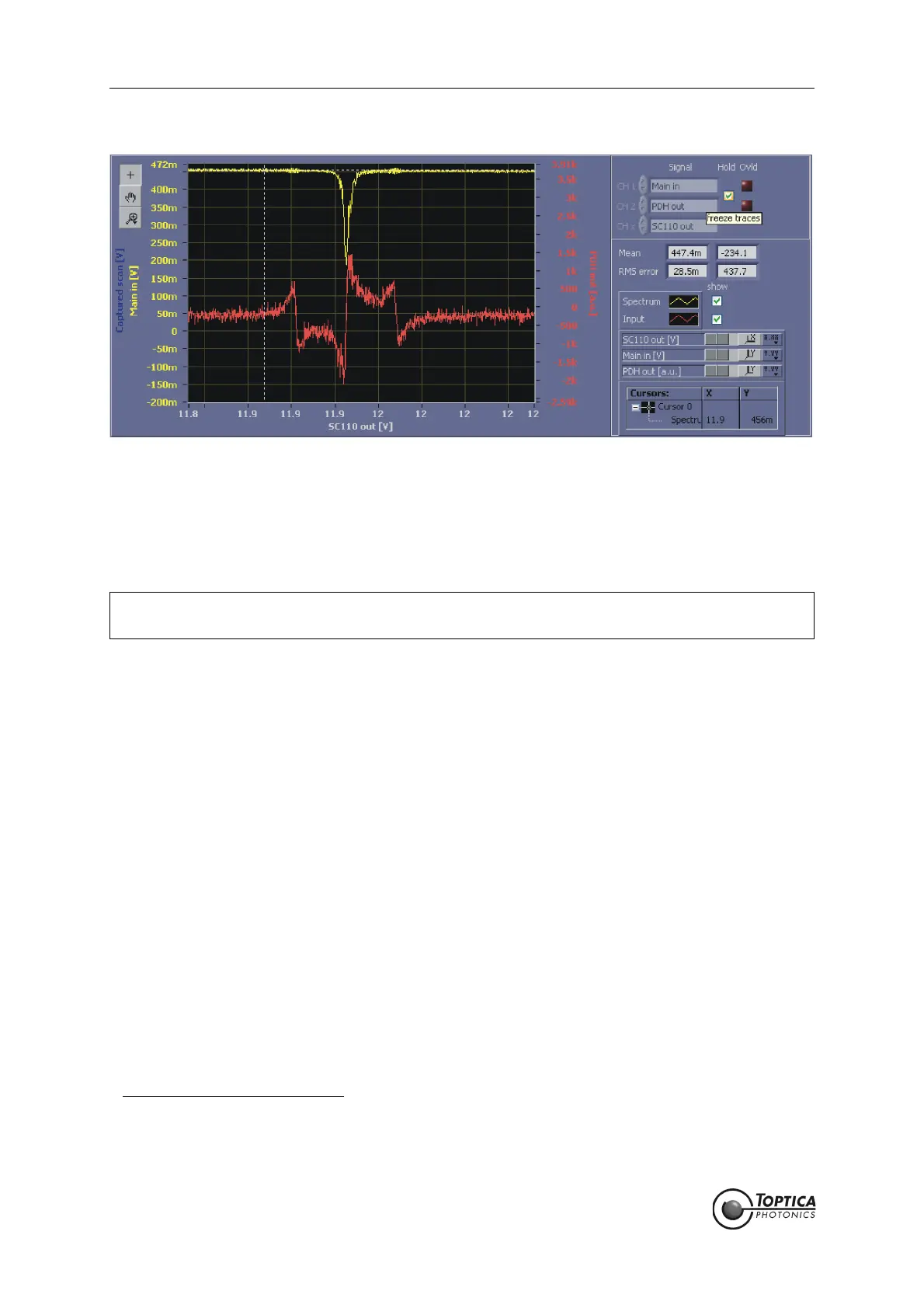
Figure 54 AutoLock display of the reflection signal of a Fabry-Perot cavity (upper yellow trace) with the
corresponding PDH-signal (lower red trace)
18a. The phase between the modulation and the reference signal must be adjusted to obtain a large,
symmetric error signal with steep slopes at the maximum of the spectral signal. The sign of the error
signal can be inverted by changing the phase by 180°. The sign should be adjusted such, that the
lock-in signal is the derivative of the input signal.
Please see section 9.2 on how to manually adjust the phase.
19a. Once the phase is adjusted, compensate for any residual offset
16
at the corresponding control of
the PDH module and check the parameters of the PID controllers. To find the correct settings of the
sign for each PID controller, please see section 9.4. For optimization of the PID parameters see sec-
tion 9.3. Now you can position the crosshairs to either a peak or a valley and they will automati-
cally track the lock point. Here, we assume the following settings:
Cursor: Track on, Snap to setpoint: on, Smart Assistance: Engage on, Setpoint: off.
When the error signal offset is compensated, the PID set point can be set to zero.
20a. To initiate the lock perform a right mouse click to access the context menu and select LI/PDH: Lock
to extremum. The trace changes its color (here from yellow to blue) to show that the actual trace
is captured in the background. During the next scan the lock is triggered. Figure 56 shows the
AutoLock display while the lock is triggered. The blue trace is the captured signal of the last scan.
The yellow trace is the scan during which the lock is triggered. You can see that the trace stops at
the selected peak. After a while the yellow trace disappears and there is only a scatter plot left.
The interpretation of this plot and the optimization of the lock can be found in section 10.2.1
17
.
NOTE ! As of software versions 1.5.4.70 the DigiLock frequency modulation modules feature an
automatic phase adjust (see section 8.2.1.7 and 8.2.1.8 for details).
16. Residual offsets in the demodulated error signal are mostly due to unintended intensity modulations that come with the
phase modulation.
17. The output of the controllers can be restricted using the Limit settings (section 8.2.1.4 and 8.2.1.5), e.g. to about the scan
range.This helps to avoid destabilization of the laser by driving it far from the lock point especially during initial setup and
optimization.
 Loading...