2.Assemblethemaster-section-valvemanifold,
gasket,andmaster-section-bypassvalvewitha
clamptightenedbyhand(Figure82A).
3.Aligntheangeofthemaster-section-valve
manifold,agasket,andtheagitation-valve
manifold(Figure82B).
4.Assemblethemaster-section-valvemanifold,
gasket,andagitation-valvemanifoldwitha
clamptightenedbyhand(Figure82B)
5.Aligntheangeofthemaster-section-valve
manifold,agasket,andthemaster-section
house(Figure82B).
6.Assemblethemaster-section-valvemanifold
andsocketwithaclamptightenedbyhand
(Figure82B).
7.Securetheend-capttingtotheoutletttingby
insertingaretainerintotheoutlettting(Figure
82B).
8.Assembletheagitationvalvetothevalvemount
withtheanged-headboltandangedlocknut
thatyouremovedinstep3ofRemovingthe
Master-Section-ManifoldValve(page64)and
torquethenutandboltto1017to1243N∙cm
(90to110in-lb).
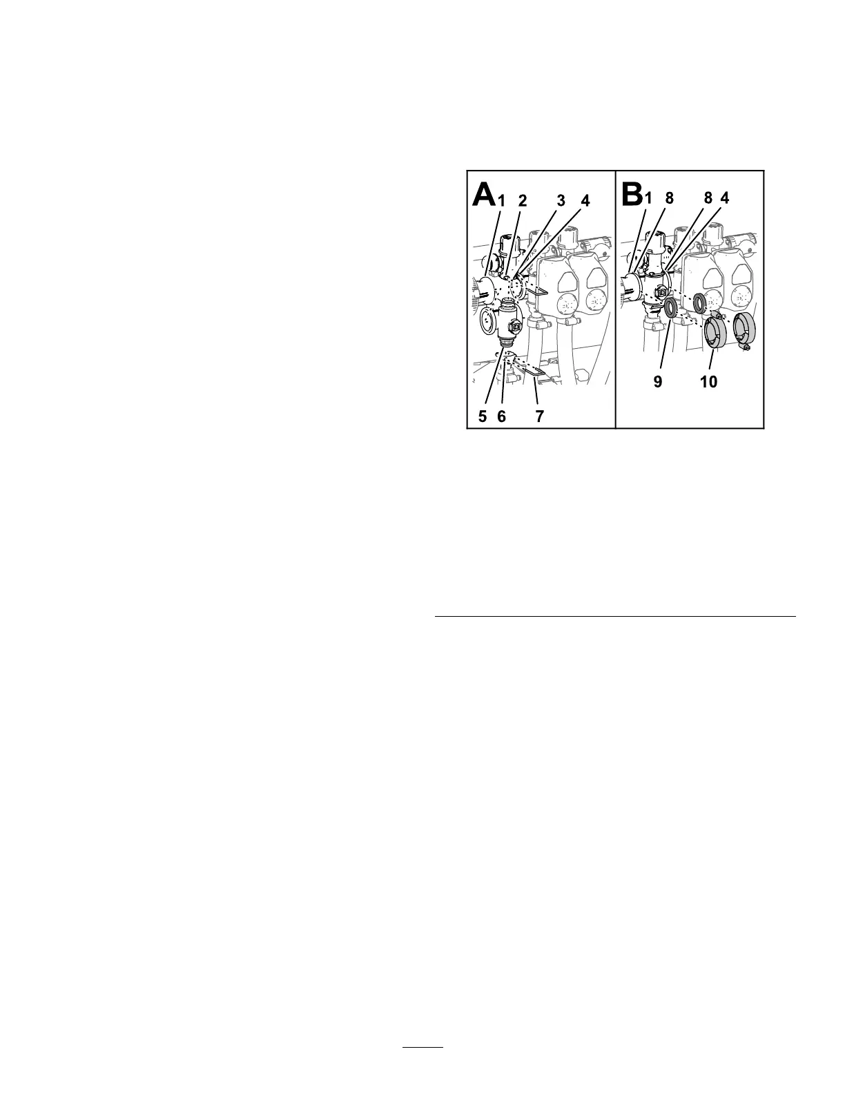
InstallingtheSectionManifold
Valve
1.Inserttheupperend-capttingofthemanifold
valveintothebypasstting(Figure83A).
Note:Ifneeded,loosenthemountinghardware
forthebypassttingtoprovideclearance.
g238558
Figure83
1.Flange(reducercoupling)6.Socket(outlettting)
2.Socket(bypasstting)
7.Retainer
3.Bypasstting8.Flange(manifold—section
valve)
4.Flange(adjacent
manifold—agitationvalve)
9.Gasket
5.End-captting(manifold
valveassembly)
10.Flangeclamp
2.Securetheend-capttingtothebypasstting
byinsertingaretainerintothesocketofthe
bypasstting(Figure83A).
3.Assembletheoutletttingontothelower
end-capttingofthemanifoldvalve(Figure
83A).
4.Securetheend-capttingtotheoutletttingby
insertingaretainerintothesocketoftheoutlet
tting(Figure83A).
5.Alignagasketbetweentheangesofthe
reducercouplingandthesectionvalvemanifold
(Figure83B).
6.Assemblethereducercoupling,gasket,and
sectionvalvemanifoldwithaclampandtighten
byhand(Figure83B).
7.Ifinstallingthe2leftmostsectionvalves,align
agasketbetweentheangesofthe2adjacent
sectionvalvemanifolds(Figure83B).
8.Assemblethe2adjacentsectionvalvemanifolds
andgasketwithaclampandtightenbyhand
(Figure83B).
70