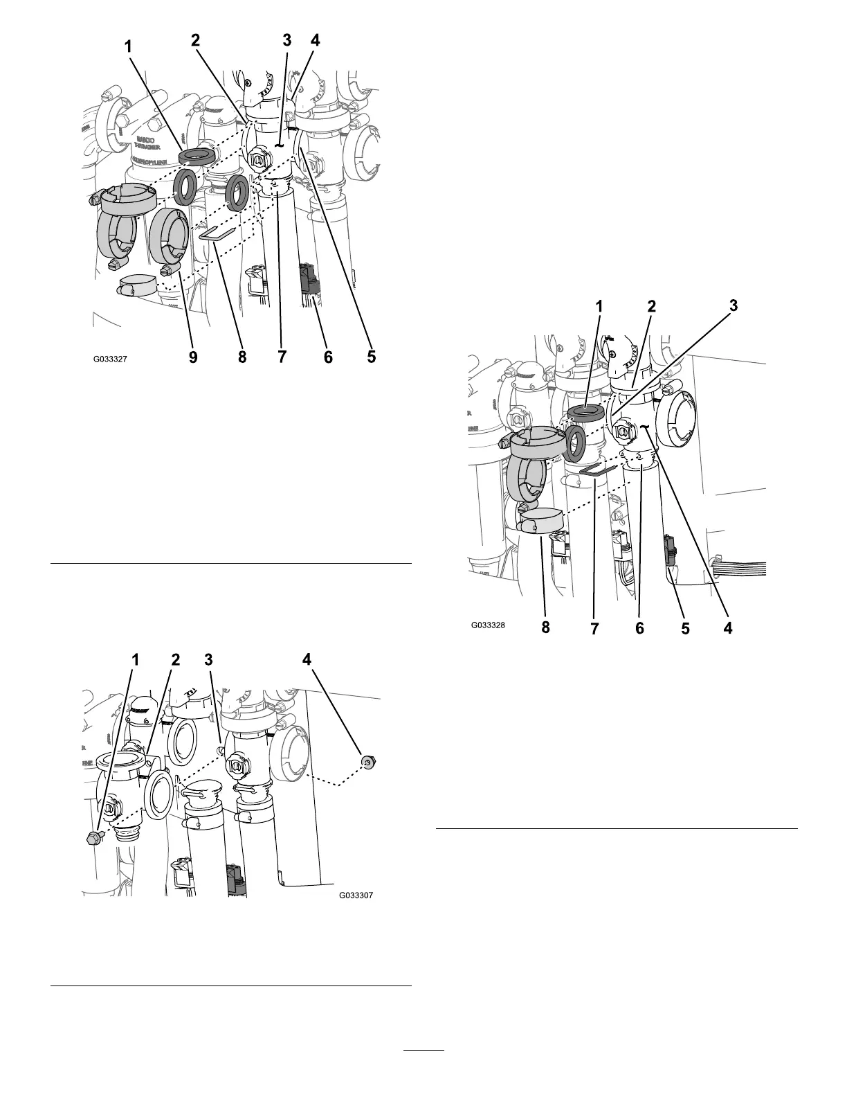
g033327
Figure69
1.Gasket6.3-pinconnector(valve
actuator—agitationvalve)
2.Flange(pressure-lter
head)
7.Socket(outlettting)
3.Manifold(agitationvalve)
8.Retainer
4.Flange(bypass
valve—agitationvalve)
9.Clamp
5.Flange(master-section
valve)
3.Removetheanged-headboltandanged
locknutthatsecurestheagitationvalvetothe
valvemountandremovethevalvemanifoldfrom
themachine(Figure70).
g033307
Figure70
1.Flanged-headbolt3.Valvemount
2.Manifold(agitationvalve)
4.Flangedlocknut
Removingthe
Master-Section-ManifoldValve
1.Removetheclampsandgasketsthatsecurethe
manifoldforthemaster-sectionvalve(Figure71)
tothemaster-section-bypassvalve,agitation
valve,andmaster-section-manifoldvalve(atthe
endofthehosefortheowmeter).
Note:Retaintheclamp(s)and
gasket(s)forinstallationinInstallingthe
Master-Section-ManifoldValve(page69).
2.Removetheretainerthatsecurestheoutlet
ttingtothemanifoldforthemaster-section
valve(Figure71).
g033328
Figure71
1.Gasket5.3-pinconnector(valve
actuator—master-section
valve)
2.Flange
(bypass—master-section
valve)
6.Socket(outlettting)
3.Flange(agitationvalve)
7.Retainer
4.Manifold(master-section
valve)
8.Clamp
3.Removetheanged-headboltandanged
locknutthatsecuresthemaster-sectionvalveto
thevalvemountandremovethevalvemanifold
fromthemachine(Figure72).
64