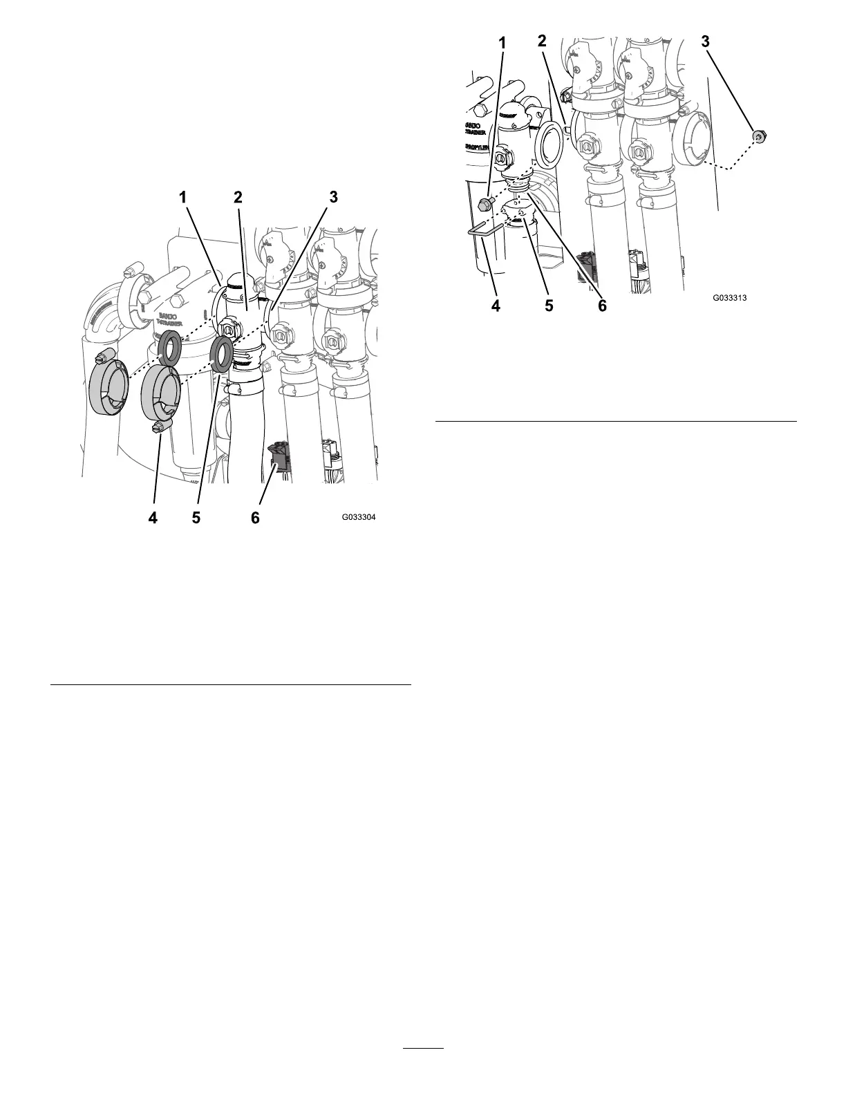
Removingthe
Rate-Control-ManifoldValve
1.Removetheclampsandgasketsthatsecurethe
manifoldfortherate-controlvalve(Figure67).
Note:Retaintheclamp(s)andgasket(s)for
installationinInstallingtheRateControlManifold
Valve(page68).
g033304
Figure67
1.Flange(pressure-lter
head)
4.Clamp
2.Manifold(rate-control
valve)
5.Gasket
3.Flange(agitationvalve)6.3-pinconnector(valve
actuator—rate-control
valve)
2.Removetheretainerthatsecurestheoutlet
ttingtothemanifoldfortherate-controlvalve
(Figure68).
g033313
Figure68
1.Flanged-headbolt4.Retainer
2.Valvemount
5.Socket(outlettting)
3.Flangedlocknut
6.Manifold-valveassembly
3.Removethe2anged-headboltsand2anged
locknutsthatsecuretherate-controlvalveto
thevalvemountandremovethevalvemanifold
fromthemachine(Figure68).
Note:Ifnecessary,loosenedthemounting
hardwareforthepressure-lterheadtoease
removaloftherate-controlvalve.
RemovingtheAgitation-Manifold
Valve
1.Removetheclampsandgasketsthatsecure
themanifoldfortheagitationvalve(Figure
69)totheagitation-bypassvalve,rate-control
valve,master-sectionvalve,andadaptertting
(agitation-throttlevalve).
Note:Retaintheclamp(s)andgasket(s)for
installationinInstallingtheAgitation-Manifold
Valve(page68).
2.Removetheretainerthatsecurestheoutlet
ttingtothemanifoldfortheagitationvalve
(Figure69).
63