InstallingtheRateControl
ManifoldValve
1.Alignagasketbetweentheangesoftherate
controlvalvemanifoldandthepressurelter
head(Figure80A).
Note:Ifneeded,loosenthemountinghardware
forthepressurelterheadasneededtoprovide
clearance.
g033311
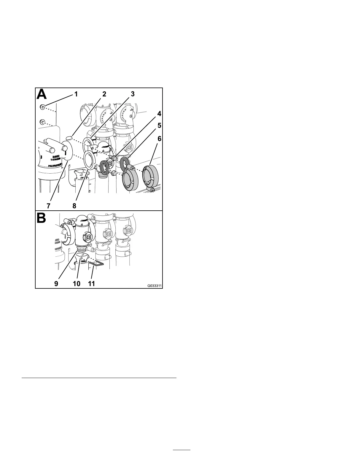
Figure80
1.Locknut(1/4
inch)
5.Gasket9.Coupling
(manifold-valve)
2.Valvemount6.Flangeclamp
10.Socket(outlet
tting)
3.Flange
(agitation-valve)
7.Flange
(pressurelter
head)
11.Retainer
4.Flanged-head
bolt(1/4x3/4
inch)
8.Flange(rate
controlvalve)
2.Assembletheratecontrolvalvemanifold,
gasket,andpressurelterheadwithaange
clampandtightenbyhand(Figure80A).
3.Alignagasketbetweentheangesoftherate
controlvalveandtheagitation-valvemanifold
(Figure80A).
4.Assembletheratecontrolvalvemanifold,
gasket,andagitation-valvemanifoldwitha
angeclampandtightenbyhand(Figure80A).
5.Assembletheratecontrolvalvetothevalve
mountwiththe2anged-headboltsand2
angedlocknuts(Figure80A)thatyouremoved
instep3ofRemovingtheRate-Control-Manifold
Valve(page63)andtorquethenutandboltto
10to12N∙m(90to110in-lb).
6.Assembletheoutletttingontothecoupling
ttingatthebottomofthemanifoldfortherate
controlvalve(Figure80B).
7.Securetheoutletttingcouplingttingby
insertingaretainerintothesocketoftheoutlet
tting(Figure80B).
8.Ifyouloosenedthemountinghardwareforthe
pressurelterhead,tightenthenutandboltto
10to12N∙m(90to110in-lb).
InstallingtheAgitation-Manifold
Valve
1.Aligntheangeoftheagitation-valvemanifold,
1gasket,andtheangeoftheagitation-bypass
valve(Figure81A).
Note:Ifneeded,loosenthemountinghardware
forthemaster-sectionvalveasneededto
provideclearance.
68