g033309
Figure72
1.Flanged-headbolt3.Valvemount
2.Manifold(master-section
valve)
4.Flangedlocknut
RemovingtheSection-Manifold
Valve
1.Removeclampsandgasketsthatsecurethe
manifoldforthesectionvalve(Figure73)tothe
adjacentsectionvalve(ifleftsectionvalve,and
thereducercoupling).
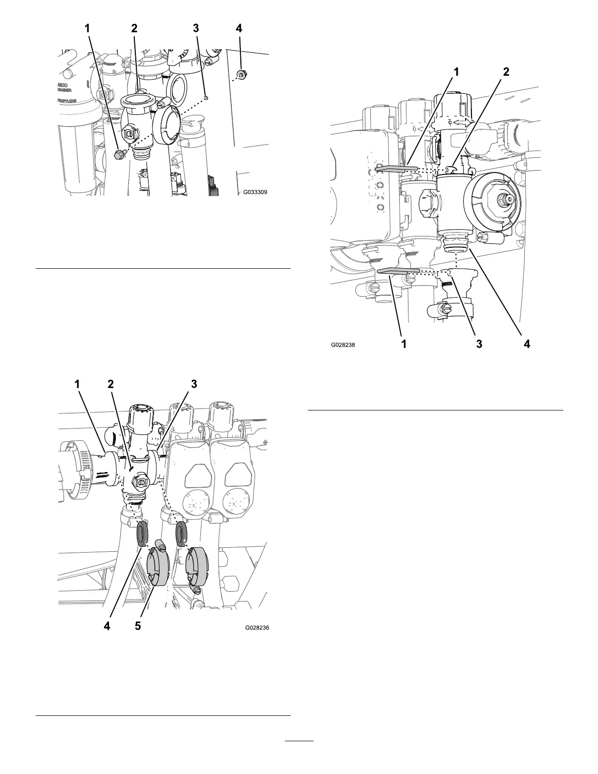
g028236
Figure73
1.Flange(reducercoupling)4.Gasket
2.Manifold(sectionvalve)
5.Flangeclamp
3.Flange(adjacentsection
valve)
2.Removetheretainersthatsecuretheoutlet
ttingtothesection-valvemanifoldandthevalve
manifoldtothebypasstting(Figure74).
g028238
Figure74
1.Retainer
3.Socket(outlettting)
2.Socket(bypasstting)4.Manifold-valveassembly
3.Fortheleftorrightsectionvalves,removethe
anged-headboltsandangedlocknutsthat
securethesectionvalve(s)tothevalvemount
andremovethevalvemanifold(s)fromthe
machine;forthecentersectionvalve,remove
thesection-valvemanifoldfromthemachine
(Figure75).
65