Machines with 127 cm (50-inch)
Mower Decks
1. Park the machine on a level surface, disengage
the blade-control switch, and move the
motion-control levers outward to the P ARK
position.
2. Shut of f the engine, remove the key , and wait
for all moving parts to stop before leaving the
operating position.
3. Remove the mower deck; refer to Removing the
Mower Deck ( page 49 ) .
4. Remove the 3 locknuts (5/16 inch) from the
welded posts of the right baf e ( Figure 13 ).
g297022
Figure 13
1. Locknut—5/16 inch (4) 3. Carriage bolt—5/16 x 3/4
inch
2. Right baf e 4. W elded post (3)
5. Remove the 2 carriage bolts and 2 locknuts
securing the right baf e to the deck and remove
the baf e ( Figure 13 ).
6. Locate the 3 bolts in loose parts and use the
existing locknuts and install these fasteners into
the holes used for the welded posts ( Figure 13 )
to prevent ying debris.
Note: Install the bolt upward, through the
underside of the deck and use an existing
locknut to secure from the topside.
7. Remove the 2 locknuts (5/16 inch) from the
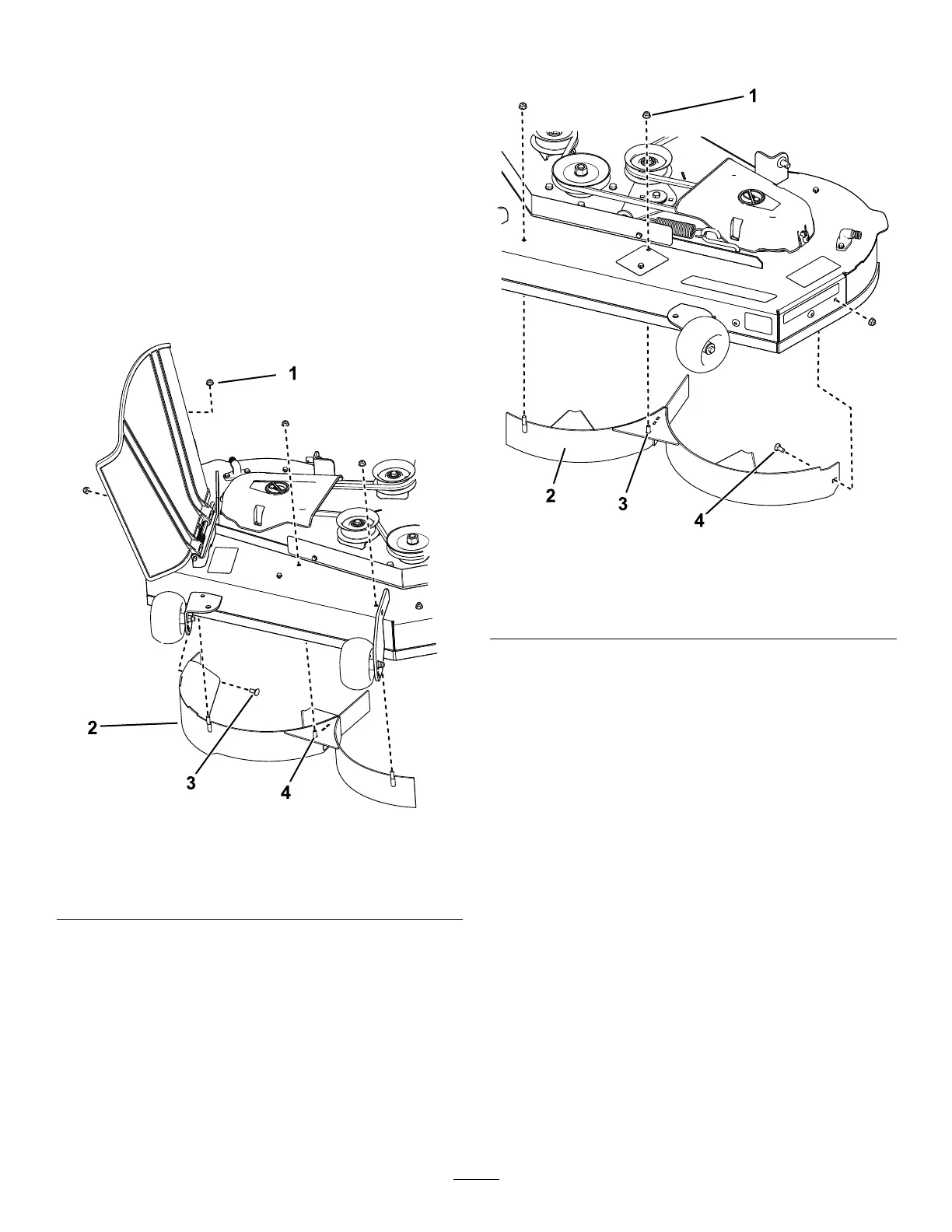
welded posts of the left baf e ( Figure 14 ).
g297021
Figure 14
1. Locknut—5/16 inch (3) 3. W elded post (2)
2. Left baf e 4. Carriage bolt—5/16 x 3/4
inch
8. Remove the carriage bolt and locknut securing
the left baf e to the deck and remove the baf e
( Figure 14 ).
9. Locate the 2 bolts in loose parts and use the
existing locknuts and install these fasteners into
the holes shown in Figure 14 on the mower deck
to prevent ying debris.
Note: Install the bolt upward, through the
underside of the deck and use an existing
locknut to secure from the topside.
10. Remove the nut from the grass deector rod
under the mower deck ( Figure 15 ).
17
 Loading...