TRANSPORTATION AND INSTALLATION MANUAL
b-2) Output signal connector HAND (Type-P)
Pin Signal name Signal No.
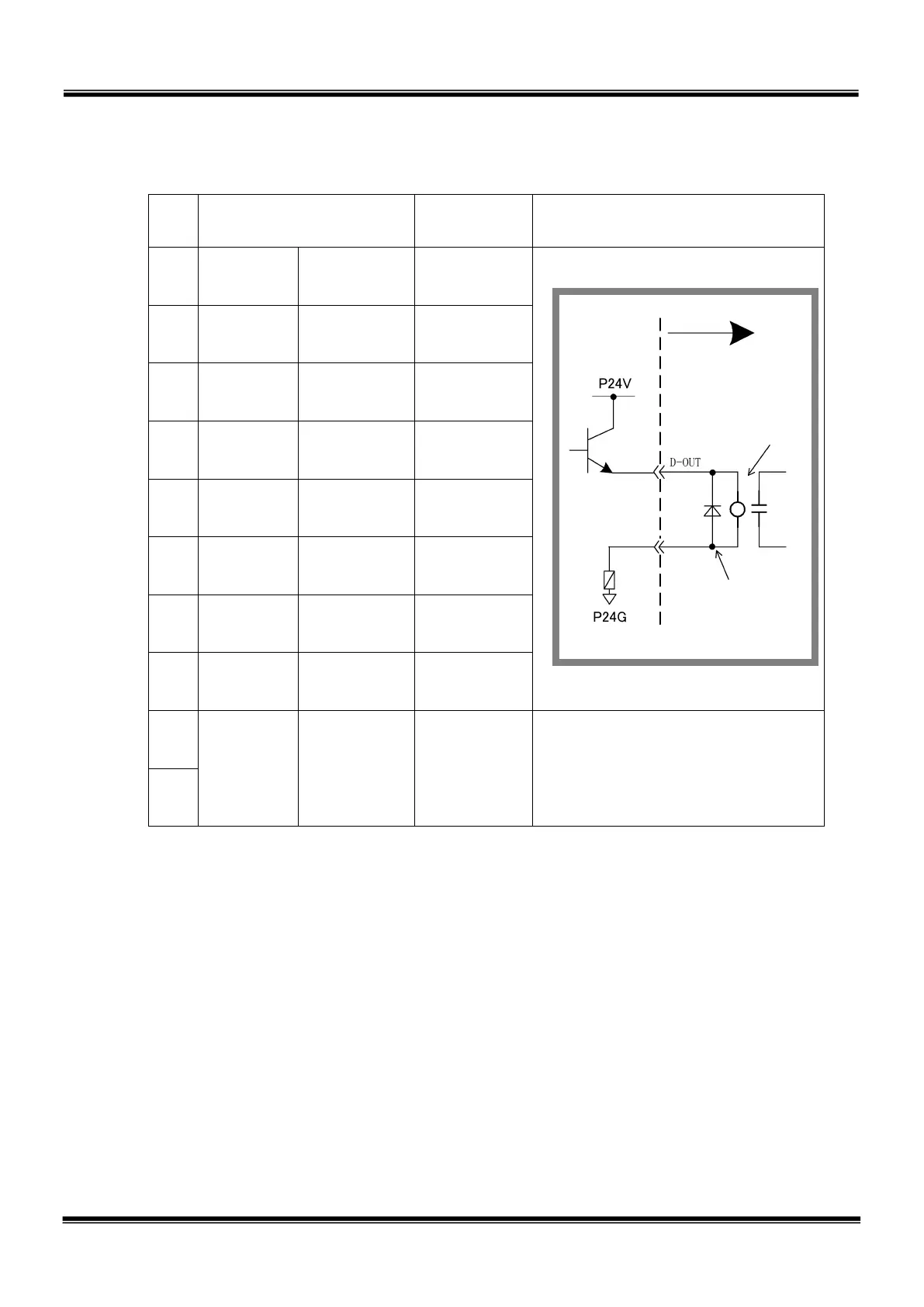
Input circuit and example of
connections
9 D-OUT0
Output
signal 0
201
10 D-OUT1
Output
signal 1
202
11 D-OUT2
Output
signal 2
203
12 D-OUT3
Output
signal 3
204
13 D-OUT4
Output
signal 4
205
14 D-OUT5
Output
signal 5
206
15 D-OUT6
Output
signal 6
207
16 D-OUT7
Output
signal 7
208
17
P24G 0 V
18
By using the P24V power of the controller, a relay, solenoid valve, etc., can be
driven. When the external power is used, GND of the external power should be
common to GND (P24G) of the robot controller.
Output specifications:
Rated voltage : DC24 V (P24V)
Rated current : 100 mA
• When a relay or solenoid valve, etc., is connected, it is necessary to use a
surge killer or diode to absorb the surge voltage.
• When a double solenoid is used, HO_1 and HO_2, and HO_3 and HO_4 are used as pairs.
The right figure shows the DC relay circuit when the external power is used.
’s side
Diode for preventing
counter electromotive
voltage
STE 85305
– 52 –

 Loading...


