TRANSPORTATION AND INSTALLATION MANUAL
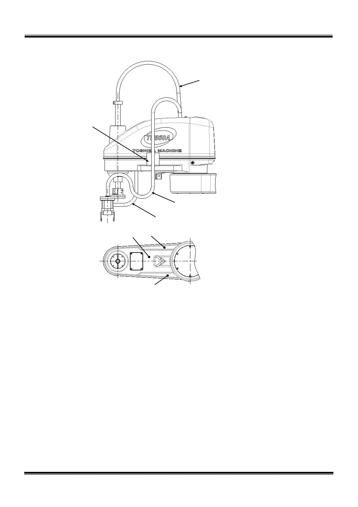
Tool connection by using the hollow hole
(18 mm
-dia.) on Z-axis ball screw shaft.
Tool connection by attaching the fixed
stays to the lower side of the arm.
Tool connection by mounting the wiring
panel on the lower side of the arm.
Fixed stay (To
be provided by
customer.)
Fig. 5.6 Wiring method
Note: For the tap holes on the lower side of the arm 2, which are used to attach the
fixed stays, it is recommended to machine surfaces A in the figure above. If
the pre-drilled hole is under 15 mm-deep at this time, it will not go through the
top surface.
Recommended tap holes machined: M4 depth 8, pre-drilled hole depth 13 mm
When machining surface B, the hole will go through the top surface (arm 2
interior). When using the robot in a clean environment, machine surfaces A
and attach the stays there.
STE 85305
– 61 –

 Loading...


