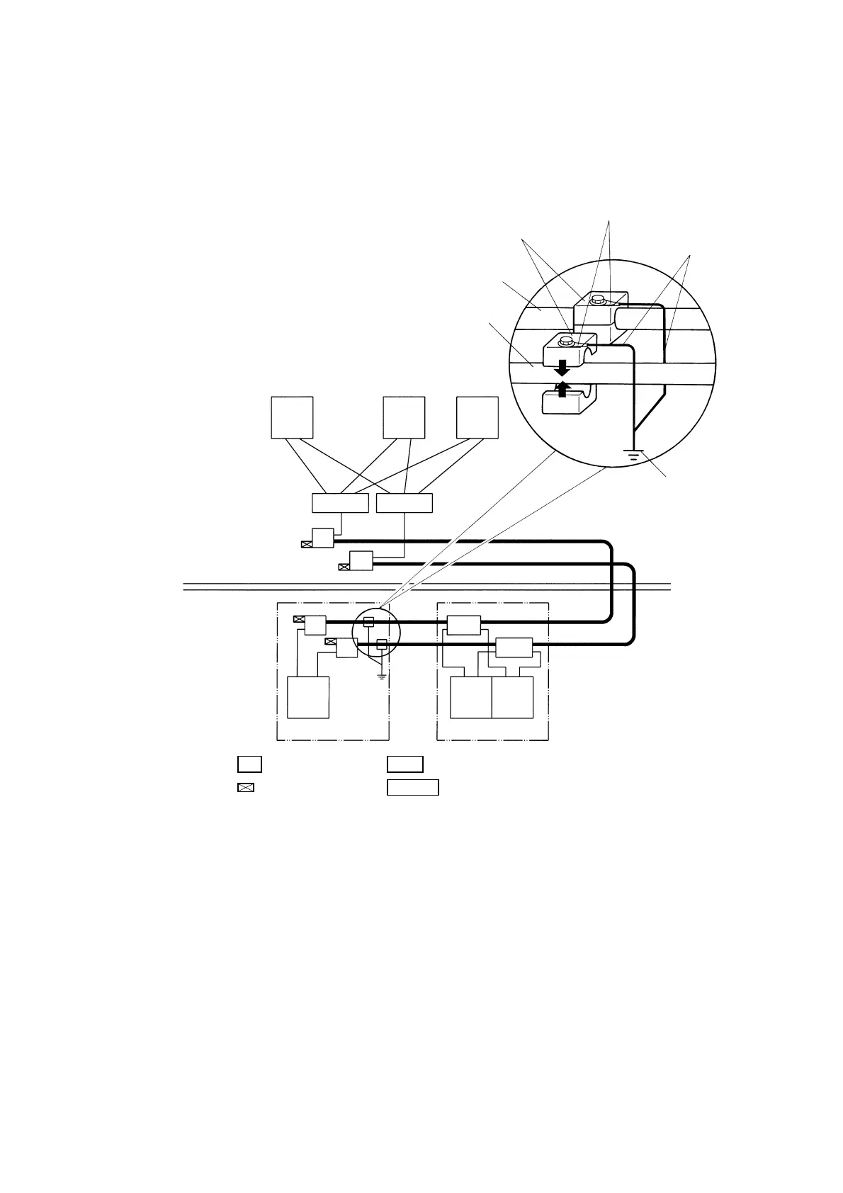
2. Wiring of PCS-DS51
29
*
Crimp the grounding
line to the lug terminal
installed to the
grounding terminal.
* Connected to FG of the
cabinet grounded with
Type 3.
For example, screw it to
the bus-bar fixed to the
cabinet.
*Grounding line
(with thickness of
more than 2mm)
Ethernet control LAN-A system
(10BASE5 coaxial cable)
Ethernet control LAN-B system
(10BASE5 coaxial cable)
Grounding terminal
Type 3
grounding
Twisted pair
cable
Field
Operator room
Coaxial cable (yellow cable)
PCS cabinet
PCS redundant cabinet
: MAU (transceiver) : Multi-port MAU (2 ch transceiver)
: Terminator
TR MTR
: HUB
HUB
MTR
MTR
TR
TR
PCS-DS PCS-DS PCS-DS
10BASE5
HUB
TR
10BASE-T
HUB
TR
SVR-DS OIS-DS OIS-DS
Figure 2.11 Grounding of Coaxial Cables
INSTRUCTION:
Since the transmission lines are based on the single point grounding, make sure to keep them from
contact with the N type connector.
Use 50
Ω
N type terminators.
The characteristic impedance of the Ethernet control LAN transmission lines is 50
Ω
. Note that there are
terminators for 75
Ω
. If the 75
Ω
terminators are used, many transmission errors may occur.
✎
 Loading...


